TM 55-2210-223-12
TO 45A2-2-14-41
2-3. OPERATOR CONTROLS AND INDICATORS (cont)
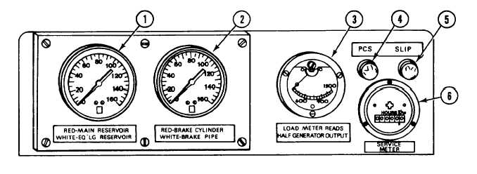
FIGURE 2-3. Gage panel.
Key
Control or Indicator
Function/Use
1
RED-MAIN RESERVOIR and
Indicates the main and equalizing air pressures.
WHITE-EQ'LG RESERVOIR
Duplex Air Gage
2
RED-BRAKE CYLINDER and
Indicates the brake cylinder and brake pipe
WHITE-BRAKE PIPE Duplex
air pressures.
Air Gage
3
LOAD METER Indicator
Indicates one-half of the output of main
generator. Indicates the current through
traction motors 1 and 2.
4
PCS Indicator Light
When lit, indicates pneumatic control system air
pressure is below 75 psi (517 kPa).
5
SLIP Indicator Light
When flashing, and warning bell is sounding,
indicates that a pair or more wheels are
slipping.
6
SERVICE METER
Indicates the number of hours the diesel engine
has run.
2-6