TM 55-2210-223-34
TO 45A2-2-14-22
3-35. EXCITER-AUXILIARY GENERATOR ASSEMBLY (cont)
TEST (cont)
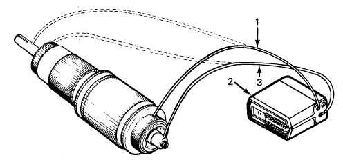
29. Perform the bar-to-bar resistance test by the following:
a.
Place lead (1) of multimeter (2) on the shaft or core of the armature.
b.
Place lead (3) of multimeter (2) on one of the commutator bars. Record reading on multimeter. Contact each
successive bar around the commutator and record each reading.
c.
If the test indicates resistance readings of 10 percent or more above the average recorded readings on 20 or
more connections, tig weld all. coil leads to commutator neck convections. If test indicates resistance readings
of 1/2 percent below the average or a full-scale meter deflection of the multimeter, there is a shorted coil to the
armature.
d.
Below average readings could indicate the presence of water in the coils. If below average readings are obtained
bake armature in a convection oven for 4 hours at 230° (110°C).
e.
Cool at room temperature and repeat step (b).
f.
If readings are still low, replace armature.
ASSEMBLY
30.
Install cooling fan (54), eight lockwashers (53), and bolts (52) on armature (55).
31.
Install armature (55) in auxiliary frame (51).
32.
Install exciter frame (50) on armature (55) and secure wih eight lockwashers (49) and bolts (48).
33.
Fill inner bearing housing (47) and bearing assembly (44) with grease.
34.
Install inner bearing housing (47) and gasket (46).
3-130