TM 55-2210-224-12
2-3. OPERATOR CONTROLS AND INDICATORS (cont)
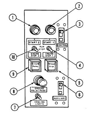
FIGURE 2-6. Engine control panel.
Key
Control or Indicator
Function or Use
(1)
ENGINE START 2 Pushbutton
Push to start No. 2 engine.
(2)
ENGINE START 1 Pushbutton
Push to start No. 1 engine.
(3)
CONTROL Circuit Breaker
Prevents overloading of locomotive control electrical system.
(4)
ENGINE STOP 1 Switch
Stops No. 1 engine. Must be in RUN position to start engine.
(5)
WHEEL SLIP Light
Indicates when one or more pairs of wheels are slipping.
(6)
AUXILIARY Circuit Breaker
Prevents overloading of auxiliary electrical system.
(7)
COWLING LIGHTS Switch
Turns cowling lights inside of engine compartment ON or OFF.
(8)
GROUND RELAY RESET
Push to reset ground relay.
(9)
GROUND RELAY Light
Indicates a ground or a current passing through the frame or body.
(10)
ENGINE STOP 2 Switch
Stops No. 2 engine. Must be in RUN position to start engine.
2-8