TM 55-2200-001-12
Change 3
Sec. 6-Fig. 82 (Rev.-9-1984)
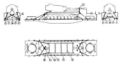
TANKS AND SIMILAR UNITS OVER 100,000 LBS.-CRAWLERS REMOVED--FLAT CARS
Item
No. of Pcs.
Description
A
Brake wheel clearance. See Fig. 2, Sec. 1.
B
2
12 1/4 in. x 16 1/2 in. · 33 in. Locate longitudinally at each end and under center of tank. Secure
each to floor with two 3/4 in. dia. bolts.
C
4
Blocks, pattern 70. Locate at each corner of tank against outside bogie wheel. Secure each to
floor with three 3/4 in. dia. bolts.
D
2
Blocks, pattern 71. Locate between the two front bogie wheels on each side. Secure each to
floor with two 3/4 in. dia. bolts.
E
12
Blocks, pattern 72. Locate between all remaining bogie wheels on each side. Secure each to
floor with one 5/8 in. dia. bolt.
F
2
6 in. x 6 in. guide rails, located against inside of bogie wheels, of sufficient length to contact
all wheels, secured to floor with three 5/8 in. dia. bolts.
G
5
6 in. x 6 in. cross braces between guide rails equally spaced, securely nailed to floor.
H
2
1 1/2 in. dia. rods. Locate on each side of rear of tank at upper eye and pass forward to stake
pocket on same side of car. Secure at upper eye with clevis and pin, and at bottom of stake
pocket through a 1/2 in. x 4 in. x 10 in. plate.
2
1 1/2 in. dia. rods. Locate on each side of rear of tank at lower eye, cross to nearest stake
pocket on opposite side of car. Secure at lower eye with clevis and pin, and at bottom of stake
pocket through 1/2 in. x 4 in. x 10 in. plate.
2
1 1/2 in. dia. rods. Locate on each side of front of tank at lifting lug and pass forward to stake
pocket on same side of car. Secure to lifting lug with clevis and pin, and at bottom of stake
pocket through 1/2 in. x 4 in. x 10 in. plate.
2
1 1/2 in. dia. rods. Locate on each side of front of tank at cable hook, cross to nearest stake
pocket on opposite side of car. Secure at cable hook with ring permanently attached to tie
rod, and at bottom of stake pocket through a 1/2 in. x 4 in. x 10 in. plate.
J
2 ea. unit.
3/8 in. steel cable, 6x19 IWRC. Apply two 3/8 in. cables in a complete loop securing gun barrel
to unit at each side. Not required when unit is equipped with external built-in gun brace;
however, if external gun brace is inoperative, cable will be used. Substitution of wire or
banding is not authorized.
When necessary to elevate tanks to comply with "Railway Line Clearances" or to permit the application of Items
"B", "C", "D" and "E", longitudinal timbers of suitable length, width and thickness may be applied underneath units
secured as shown in Figure 81.
Longitudinal center line of tank must be directly over longitudinal center line of car.
Tank must be jacked 2 in. for application of Items "B".
Turret gun should be in straight forward position and turret lock handwheel and elevating mechanism handwheel
must be wired to prevent rotating.
Detached parts, (including crawlers), must be secured in such a manner as to prevent their movement on car in
transit.
See General Rules 4, 5, 7, 9, 11, 14, 15, 19 and 19-A for further details.
E-106