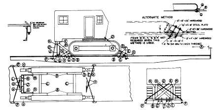
Sec. 4-Fig. 21 (Rev.--3-1965)
CRAWLER TYPE MACHINES-ROTATING BODIES-BOOMS DETACHED--FLAT CARS
Item No. of Pcs.
Description
A
2
Brake wheel clearance. See Fig. 2, Sec. 1.
B
2
4 in. x 6 in., hardwood, length equal to that portion of crawler tread resting on floor. Locate on floor,
against crawlers, and secure each with four 5/8 in. dia. bolts or eight 60-D nails. Substitute, if desired,
four pieces, 4 in. x 6 in. x 4 ft. Locate as shown and secure each with two 5/8 in. dia. bolts or four 60-
D nails.
C
2
4 in. x 4 in., hardwood, long enough to fit between items "B". Secure each to floor with two 5/8 in. dia.
bolts or four 60-D nails.
D
4
4 in. x 6 in. x 21 in., hardwood, for machines weighing 45,000 lbs. or less; 6 in. x 6 in. x 21 in.,
hardwood, for machines weighing over 45,000 lbs. Toe-nail each to floor with four 40-D nails. Not
required when items "P" and "Q" are used.
E
4
6 in. x 6 in., hardwood, length to suit. Locate on top of items "D", with one end against crawler and secure
each with two 5/8 in. dia. bolts, items "F". Not required when items "P" and "Q" are used.
F
8
5/8 in. dia. bolts, with nuts and washers, long enough to pass through items "E", "G" and floor.
G
As required.
4 in. x 4 in. x 18 in., hardwood cleats, or 1/2 in. x 4 in. x 18 in. plates.
H
4
2 in. x 4 in. x 18 in., hardwood. Locate on floor with one end against item "E" and secure each with six
30-D nails.
J
1
4 in. x 6 in., hardwood, length to suit, for machines weighing 45,000 lbs. or less; 6 in. x 6 in., hardwood,
for machines weighing over 45,000 lbs. Secure to floor with four 5/8 in. dia. bolts, with nuts and
washers.
K
As required.
Two 4 in. x 6 in., hardwood, for machines weighing 45,000 lbs. or less; two 6 in. x 6 in., hardwood, for
machines weighing over 45,000 lbs. to 120,000 lbs.; four 6 in. x 6 in., hardwood, for machines
weighing over 120,000 lbs. They must be long enough to fit between item "J" and body of machine.
L
2
2 in. x 6 in., hardwood, length to suit. Locate against item "J" and secure each to floor with six 30-D nails.
M
2
2 in. x 6 in., hardwood, length to suit. Secure top ends to items "K" and bottom ends to items "B" with four
30-D nails at each location.
N
2
2 in. x 6 in., hardwood, length to suit. Locate diagonally and secure ends to opposite items "K" with six
20-D nails at each location.
O
4
1 1/4 in. diameter rods. Attach two at front and two at rear of rotating portion and pass through opposite
stake pockets and items "P". 1 in. diameter rods may be used on machines weighing 45,000 lbs. or
less. Substitute, if desired, 5/8 in. x 6 x 7 steel cable, doubled, for 14 in. diameter rods, or 1/2 in. x 6 x
19 steel cable, doubled, for 1 in. diameter rods. Items "O" may be applied at front end of machine,
crossed between rotating portion and crawler structure, or applied on same side of machine equipped
with two brackets cast integral on both rotating and crawler structures, providing two additional rods are
applied attached to crawler structure and passed through opposite stake pockets and items "P" or
through floor and items "G".
P
1 ea. Item "O"
1/2 in. x 4 in. x 10 in. plates. Not required when items "O" consists of cable.
Q
4
8 in. x 8 in. x 36 in., hardwood, cut to fit contour of crawler treads, for machines weighing 45,000 lbs. to
120,000 lbs. Secure each with three 3/4 in. dia. bolts through floor and item 12 in. x 12 in. x 36 in.,
hardwood, cut to fit contour of crawler treads, for machines weighing over 120,000 lbs. Secure each
with three 7 8 in. dia. bolts through floor and item "G" Not required when items "D" and "E" are used.
R 42 in. x 12 in. x 36 in., hardwood cleats, for machines weighing 45,000 lbs. to 120,000 lbs.
3 in. x 4 in. x 18 in., hardwood cleats, for machines weighing over 120,000 lbs.
Locate on floor against items "Q" and secure each to floor with six 30-D nails.
Not required when items "D" and "E" are used.
Loading machines with treads extending beyond floor of car is permitted, provided machines are centrally located on car and
not more than one-half of tread extends beyond outside face of side sill.
Machines equipped with locking devices, including those with adjustable treads, should have such devices placed in locked
position by shippers.
For proper location of load on car, See Fig. 34.
See General Rules 4, 5, 9, 14, 15, 19 and 19A for further details.
F-34