TM 55-2210-224-12
2-3. OPERATOR CONTROLS AND INDICATORS (cont)
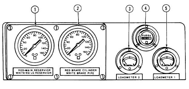
FIGURE 2-3. Gage panel.
Key
Control or Indicator
Function or Use
(1)
RED-MAIN RESERVOIR and
Indicates the main reservoir and equalizing reservoir air pressures.
WHITE-EQ'LG RESERVOIR
Duplex Air Gage
(2)
RED-BRAKE CYLINDER and
Indicates the brake cylinder and brake pipe air pressures.
WHITE-BRAKE PIPE Pressure
Duplex Air Gage
(3)
LOAD METER 2 Indicator
Indicates the output of main generator No. 2. Indicates the current
through traction motors 3 and 4.
(4)
SERVICE METER
Indicates total operating time of locomotive.
(5)
LOAD METER 1 Indicator
Indicates the output of main generator No. 1. Indicates the current
through traction motors 1and 2.
2-5

