
h. Grinding Valves.
(a) Use prepared grinding compound
for this purpose, or make a thin
paste of very finely ground pumice
and machine oil. Apply a little
grinding compound on the valve
seat, put valve in place and spin
back and forth with a screwdriver
until seat is tight. Remove pumice
before testing for a leaking valve.
(b) When grinding the lower valve,
leave the upper stem in place to act
as a guide. After grinding, clean the
stems and valve seats thoroughly,
by using a little gasoline and
blowing out with air.
(2) Inverted valve.
(a) Use compound as described in
(1)(a) above.
Spin valve with
grinding tool as shown in figure 29
for grinding lower seat and with
screwdriver for upper seat.
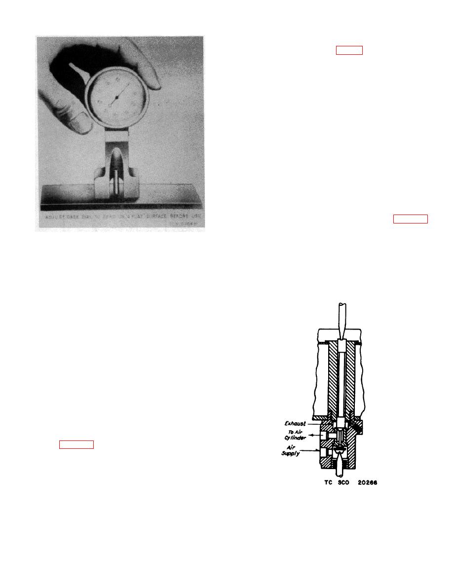
Figure 27. Micrometer dial gage for adjusting
magnet valves.
(b) Clean pushrods and seats as
described in (1)(b) above.
(3) In service, it is permissible to allow the
i. Valve Bushings.
pushrod to wear until the final gap is
(1) Valve bushings are furnished with the
approximately 0.032 inch. Some magnet
vertical portholes pilot drilled and the
cores (used with clapper type armature)
valve seats completely machined.
are made with bronze residual stops,
0.020 inch ill height above the core face.
Obviously, on cores using these pins, the
final air gap setting would be 0.012 inch
more than the height of the residual pins.
The 0.056-inch gage will at this point fail
to unseat the exhaust port to discharge air
from the cylinder and the pushrod must be
stretched by peening or a new rod used.
No adjustment of the floating valve is
possible, therefore when the maximum
travel exceeds the limit of approximately
0.012 inch, a new valve must be ground
in.
g. Standard Micrometer Dial Gage.
A more
accurate method of measuring valves is by use of a
standard micrometer gage with a special fixture, as
shown on figure 27. This is especially convenient where
there is a large number of valves to be overhauled, as
the amount of material to be removed from new valves
can be determined directly rather than by the cut and try
process.
Figure 28. Method of grinding standard valve.
54

