TM 55-2200-001-12
Change 2
Sec. 6-Fig. 51 (Rev.--4-1980)
(Drawing Redrawn 9-1977)
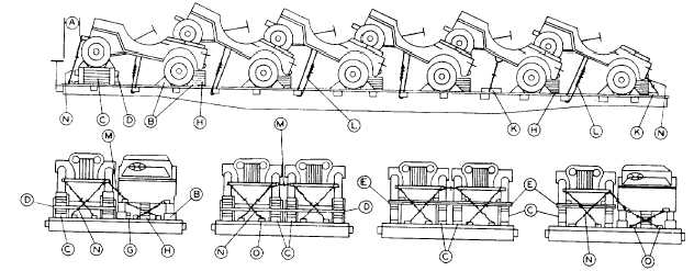
1/4 TON, 4 X 4 TRUCKS, LENGTHWISE, INCLINED, SINGLE OR DOUBLE ROWS--FLAT CARS
Item No. of Pcs.
Description
A
Brake wheel clearance. See Fig. 2.
B
2 ea. rear wheel,
Blocks, pattern 25. Locate 53 degree portion of block against front and rear of front wheels of
all units and 2 ea.
first unit in each row, against front and rear of outside rear wheels and against rear of Inside
front wheel of
rear wheels of all units. Secure heel of block to floor with three 40-D nails and toe-nail that
first unit in ea.
portion under tire to floor with two 40-D nails. Blocks on top of Items "C", pattern 41, to be
row.
nailed in same manner to Items "C". Substitute, if desired, blocks, pattern 17,18 or 67 at each
location.
C
4
Front wheel supports, pattern 41. Locate under front wheels of first unit in each row. Secure to
floor with three 30-D nails in each end and toe-nail bottom pieces to floor with two 30-D nails
on each side. Substitute, if desired, supports, pattern 42. Secure each to floor with six 30-D
nails.
D
4
2 in. x 4 in., long enough to extend to outside face of adjacent Items "C", pattern 41. Not
required when Item "C", pattern 42, is used.
E
As required.
Each to consist of two pieces of 2 in. x 4 in., long enough to extend to outside face of Items "C",
pattern 42. Locate in front and rear of front wheels of first unit, or units, in each row. Secure
lower piece to Items "C" with two 30-D nails at each location and top piece to one below with
three 30-D nails near each end. Not required when Items "C", pattern 41, are used.
F
2ea. unit.
Blocks, pattern 43. Locate one on seat box of all units except rear unitin each row.
G
1 ea. inside rear
Each to consist of two pieces of 2 in. x 4 in. x 18 in. Locate against inside face of rear wheel.
wheel.
Secure lower piece to floor with four 30-D nails and top piece to one below in like manner. Not
required when frame, Item "J", is used.
H
1 ea. unit.
Fill space between floor and rear of each unit with 2 in. x 8 in. x 12 in. pieces. Secure pieces to
each other with three 10-D nails in each and toe-nail to floor with four 30-D nails.
J
1 ea. unit.
Frame, pattern 44. Locate on floor, under rear wheels. Secure each horizontal piece to floor
with sixteen 30-D nails. Use optional on cars 9 ft. 4 in. wide or over.
K
1 ea. unit.
2 in. x 4 in. x 18 in. Secure to floor, lengthwise of car, with four 30-D nails in each. Not required
when Items "L" are attached to stake pockets.
L
1 ea. vehicle.
Wire rope, 3/8 in., 6 x 19, IWRC, doubled. Pass over top and around frame to stake pocket on
car. Metal fillers or thimbles sufficient to provide a suitable radius must be used to protect wire
rope at stake pockets and at vehicle tiedown point and must be applied so as to prevent
dislodgment. Cable clips must be applied in accordance with General Rules 15d and 15n. If
wire must be used i8 strands) pass over top and around frame and through stake pockets or
underneath and around Item "K".
M 1 ea. side by side
4 strands, No. 8 ga. black annealed wire. Pass through bumpers of adjacent units.
unit.
N
2 ea. end unit.
6 strands, No. 8 ga. black annealed wire. Pass around front and rear bumpers and underneath
and around Items "O".
O
2 ea. end unit.
2 in. x 4 in. x 18 in. Secure each to floor lengthwise of car, on top of Items "N", with four 30-D
nails.
Notes:
1. Load should be started at brake shaft end of car.
2. Units in both rows may face in same direction when width of car will permit, or when Items '"'J" are used.
3. Hand brakes must be set and levers wired or blocked.
See General Rules 1,2, 3, 4, 5, 9, 11, 14, 15, 19-A and 19-B for further details.
E-64


