TM 55-2200-001-12
Change 3
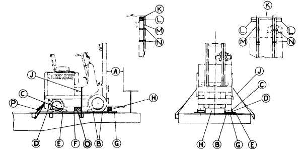
Sec. 6-Fig. 54 (Rev.-9-1984)
(Drawing Redrawn 9-1984)
FORK LIFT TRUCKS-FLAT OR GONDOLA CARS
Item No. of Pcs.
Description
A
Brake wheel clearance. See Fig. 2.
B
8 per unit.
Blocks, pattern 82, for units weighing under 15,000 lbs.; and blocks, pattern 16, chamfered at
rear for application of Items "F" and "G", for units 15,000 lbs. and over. Locate 45 degree
portion of block against front and rear of wheels. Secure each to floor with three 40-D nails.
C
As required.
Suitable material, such as waterproof paper, burlap, etc. Locate between Items "D" and tires.
D
4 per unit.
1 in. x 4 in., length to suit. Locate against Items "B", as shown, and secure to each Item "B" with
two 20-D nails.
E
4 per unit.
2 in. x 4 in., length to suit. Locate against Items "D", as shown, and secure each to floor with five
30-D nails.
F
2 per unit.
2 in. thick, width and length to suit. Locate, as shown, between inside Items "B" and ends of
Items "D". Secure each to floor with four 30-D nails.
G
4 per unit.
2 in. thick, 15 in. in length, width to suit. Locate, as shown, against outside Items "B" and ends of
Items "D", and secure each to floor with four 30-D nails.
H
1 ea. unit.
Thickness width and length to suit. Locate under lifting fork at front and toe-nail to floor with four
40-D nails. Not required when forks are detached.
J
1 per unit.
1 1/4 in. x .050 in. high tension band. Locate as shown and secure to opposite stake pocket.
Where two units are loaded side-by-side, pass Item "J" across both units and secure to
opposite stake pocket. On units loaded in gondola cars, attach Item "J" to floor with anchor
plates, pattern 84. Secure each with eight (8) 20-D cement coated nails.
K
1 ea. unit.
2 in. x 6 In., length to suit. Locate on top of truck mast.
L
2 per unit.
2 in. x 4 in. x 6 in. block. Locate against outside edge of truck mast under Item "K", as shown.
Secure to Item "K" with two 20-D nails.
M
2 per unit.
1 in. x 6 in., length to suit. Locate on front side of truck mast with end of Item "M", even with top
edge of Item "K", as shown. Secure with three 8-D nails.
N
4 per unit.
1 1/4 in. x .035 in. high tension bands. Locate as shown, suitably spaced on forks and mast. If
required, apply cushioning under bands at all sharp corners or 90 degree corners on steel
parts.
O
2 per unit.
Stabilizer block, thickness, width and length to suit. Locate under each side of fork lift frame.
Secure to car floor with four (4) 60-D nails each. Use required only on rough terrain
hydraulically pressured fork lifts.
P
2 per unit.
3/8 in. 6 x 19 IWRC wire rope. Apply one complete loop on each side between the towing
provision of the tractor and stake pocket on each side of car.
On units equipped with a single rear wheel, and, or where wheel blocking, Items "B", cannot be used, adequate
blocking must be applied at both ends and sides of unit.
Hand brakes must be set and levers wired or blocked.
Lifting forks must be placed and secured in lowered position, except when detached and secured to top of truck
mast.
Items "K", "L", "M" and "N" not required unless fork is detached and secured to truck mast.
See General Rules 1, 2, 3, 4, 5, 9, 11, 14, 15, 19-A and 19-B for further details.
E-68


