Sec. 6-Fig. 56-A (New-10-1966)
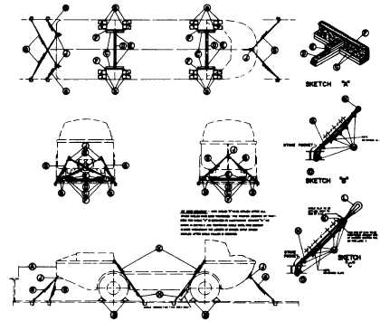
VEHICLE, AMPHIBIAN, LARC 5-FLAT CARS
Item
No. of Pcs.
Description
A
Brake wheel clearance. See Fig. 2, Sec. 1.
B
16
Blocks, pattern 15. Locate two in front and two in rear of each of the four wheels, and secure
to floor with two 60-D nails in the heel of block and two 40-D nails in each side of block.
C
4
Rub rail assemblies; see Sketch A. Nail 2 in. x 8 in. x 36 in. vertical member to the lower
piece of 2 in. x 4 in. x 36 in. with five 12-D nails. Position this assembly with 2 In. x 8 in.
Against tire and secure to floor of car through 2 In. x 4 in. with five 20-D nails. Secure
second 2 in. x 4 in. x 36 in. to the lower 2 in. x 4 in. with five 20-D nails.
D
2
Each to consist of two pieces of 2 in. x 4 In. lumber, length equal to distance between Items
"C". Secure lower piece to floor with 20-D nails spaced 8 in. apart staggered. Nail top piece
to lower piece in a like manner.
E
4
Each to consist of two pieces of 2 in. x 4 in. x 24 in. Nail to Items "C" and "D" using eight
20-D nails in each piece.
F
4
Suitable protective material between tires and rub rail assemblies.
G
6
Y In. diameter cable, 6 x 19 improved plow steel with independent wire rope core. Form
complete loop with 14 in. overlap. See Sketch B for fittings.
H
4
- In. diameter cable, 6 x 19 improved plow steel with independent wire rope core. Form
complete loop with 26 in. overlap. See Sketch C for fittings.
J
3
Shackles. For vehicles having a 1 1/16 in. diameter hole in the towing bracket, use a 1 in.
Diameter pin with a 7/8 in. steel galvanized coated anchor shackle. For vehicles having a
larger hole in the towing bracket use an appropriate size pin and shackle. Attach the shackle
to the towing bracket and secure the pin with a cotter key.
K
4
2 in. x 4 in. x 14 1/2 in. wood protective spacer between cable and side of vehicle. Secure to
cable with staples.
L
4
Rubber hose protective spacer, 15 in. long. See Sketch C.
M
64
5/8 in. cable clips, "U" type only.
N
6
5/8 In. closed thimble at load end of bow and stern cables.
0
10
5/8 in. open thimble at all stake pockets.
Note.-Tire Pressure must be reduced to 25 p.s.i., prior to applying cables, Items "G" and "H". After Items "O" and "H" are
installed they are to be tightened with a come-a-long or other suitable tensioning device. See General Rules 3, 4, 5, 7, 9,
14, 15, 19-A, 19-B for further details.
E-70