Sec. 6-Fig. 71 (Rev.-9-1977)
(Drawing Redrawn 9-1977)
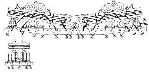
SEMI-TRAILER, 10 TON, WITH FOUR CENTER DUAL WHEELS, DOUBLE DECKED-FLAT CARS
Item
No. of Pcs.
Description
A
Brake wheel clearance. See Fig. 2, Sec. 1.
B
24
Blocks, pattern 16. Locate 45 degree portion of block against front of each front dual wheel and
at rear of each inside dual front wheel, and at rear of each rear dual wheel and at front of
each outside dual rear wheel. Secure heel of block to floor with three 40-D nails and toe-nail
that portion under tire with two 40-D nails.
C
8
Each to consist of one piece of 2 in. x 6 in. x 36 in. lumber and three pieces of 2 in. x 4 in. x 36
in. lumber. Nail the 2 in. x 6 in. x 36 in. piece to the edge of the bottom 2 in. x 4 in. x 36 in.
piece with five 12-D nails. Place suitable protective materials, such as waterproof paper or
burlap, etc., under the 2 in. x 4 in. piece and between the tire and the 2 in. x 6 in. piece, the
top portion to extend 2 inches above the 2 in. x 6 in. piece. Nail 2 in. x 4 in. piece to car floor
with four 20-D nails. Nail the other two pieces of 2 in. x 4 in. x 36 in. lumber to the one
below in the same manner. See blocking pattern 89 Section 6 material chart.
D
2
2 in. x 6 in. x 36 in. Locate under tow bars of units, as shown, and secure to floor with three
30-D nails.
E
2
Blocks, pattern 68. Locate against outside of tow bars of units, as shown, and toe-nail each
to floor with four 40-D nails.
F
2
2 in. x 6 in. x 12 in. Locate against Item "E", as shown, and secure each to floor with three
30-D nails.
G
2
Supports, built up of 6 in. x 6 in. uprights, and 4 in. x 6 in. cross pieces, 2 in. x 6 in. diagonals
and braces, and 2 in. x 6 in. floor cleats. Locate under end of units at least 6 in. from king
pin or landing gear.
H
12
3/4 in. dia. bolts. Locate three on each side of each unit. Pass through 1/4 in. x 3 in. x 6 in. plate,
stake pockets of top and bottom units, suitable filler blocks between units, and plate under-
neath.
J
8 ea. unit.
Wire rope 1/2 in., 6 x 19, IWRO, single strand. Locate as shown from tiedown device on trailer
to stake pocket. Apply wire rope at approximately 45 degree angle. Secure wire rope at each
end with three 1/2 in. cable clips. Thimbles must be used at stake pockets to protect wire
rope. Secure thimbles to wire rope with one 1/2 in. cable clip.
K
1
2 in. x .050 in. high tension band. Pass over tow bars of units and secure underneath Items
"F", or to opposite stake pockets.
L
As required.
Blocks, width, thickness and length to suit. Locate between frame of top unit and springs on
each side. Secure in position with two 1 1/4 in. x .035 in. high tension bands encircling both
blocks at ends.
See General Rules 1, 2, 3, 4, 5, 7, 9, 11, 14, 15 and 19-B for further details.
E-93