Sec. 6-Fig. 78-A (Rev.-10-1968)
LANDING VEHICLES, TRACKED, (LVT TANKS), WITH OR WITHOUT GUNS, OVER 60,000 TO 100,000
LBS. INCLUSIVE-FLAT CARS
Item
No. of Pcs.
Description
A
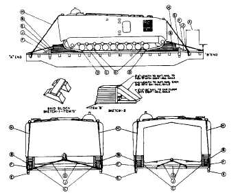
Brake wheel clearance. See Fig. 2, Sec. 1.
B
4 ea. unit.
Blocks, 3 in. x 6 in. length to suit, laminated. Secure lower pieces to floor with 40-D nails
every 8 in., staggered. Secure upper pieces to ones below in like manner. Inner ends are
to be beveled to fit contour of tracks. Height of complete blocks must be on a plane with
the center line of the front and rear drive sprockets and compensating idler wheels.
C
2 ea. unit.
Each to consist of two pieces of 3 in. x 6 in., length to suit. Locate from apoint beginning
at the center of the first bogie wheel and extending longitudinally to a point at the center
of the rear bogie wheel. Locate bottom pieces on floor against inside of treads, with 40-D
nails every 18 in., staggered. Secure upper pieces to ones below in like manner. Position
on car prior to lifting or driving vehicle in place.
D
4 ea. unit.
Each to consist of two pieces of 3 in. x 6 in., length to suit. Position transversely, one at each
end between Item "C", and the remaining two evenly spaced between the two end pieces.
Secure to floor with two 40-D nails for each piece. Fasten upper pieces to ones below in
like manner. Position on car prior to lifting or driving vehicle in place. Substitute (in lieu
of Items "C" and "D"), if available and desired, eight 1/4 in. stock mild steel cleats, per
Pattern 75. Position two each corner inside of tracks, spaced 28 1/4 in. apart, center to
center, one on each side of end bogie wheel.
E
4 ea. unit.
Hardwood stakes. Size to fit stake pocket. Position at ends to about a minimum of first five
layers of Item "B" above car floor, and 4 in. below bottom of stake pocket. Drive nail into
stakes, bend upward over edge of stake pocket. Substitute, if Item "E" cannot be used
as shown, blocking method indicated in Sketch 2.
F
4 ea. unit.
Hardwood pieces same size as Item "E", length to fit from top of Item "E" to floor of car.
Bevel each end and secure from Item "E" to floor of car with two 30-D nails each end.
Position at a 30 degree angle. Not required when blocking per Sketch 2 is used for Item "E."
G
4 ea. unit.
Skid block assembly, Sketch 1. Each to consist of two pieces of 6 in. x 6 in. x 18 3/8 in. hardwood,
cut to fit contour of bogie wheels, with one piece each of 3 In. x 6 in. x 20 1/2 in. hardwood
fastened to tops of the two pieces with two 40-D nails each end. Locate on tracks as
Indicated.
H
4 ea. unit.
Rods 1 1/4 in. dia., length to suit. Extend from front and rear mooring bits through stake
pockets and 1/2 in. x 4 in. x 10 in. plate underneath stake pockets. Substitute, if desired,
5/8 in. dia. 6 x 19 IWRC wire rope, applied in a complete loop and secured with four 5/8 in.
cable clips.
J
4 ea. unit.
Rods 1 1/4 in. dia. length to suit. Extend from front and rear towing eye or hooks through
stake pockets (either side or end) and 2 in. x 4 in. x 10 in plates. Substitute, if desired,
5/8 in. dia. 6 x 19 IWRC wire rope, applied in a complete loop and secured with four 5/8 in.
cable clips.
For loads superimposed above car floor, use method illustrated in Fig. 81, of Sec. 6.
"NOTICE"
This figure, when applicable, may be used for the loading of vehicles being shipped under the provisions of ICC Special
Permit No. 3498 during a National Emergency providing the gross weight per vehicle does not exceed 100,000 pounds. For
vehicles having a gross weight exceeding 100,000 pounds each, use Figure 81, Sec. 6.
See General Rules 3, 4, 5, 7, 9, 10, 14, 15 and 19-A for further details.
E-99