TM 55-2200-001-12
Change 3
Sec. 6-Fig. 79 (Rev.-9-1984)
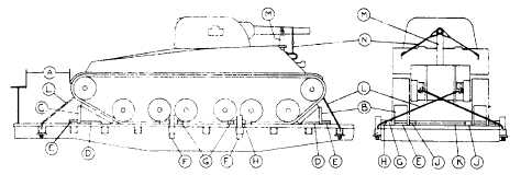
TANKS AND SIMILAR UNITS, 60,000 LBS. AND UNDER-FLAT CARS
Item
No. of Pcs.
Description
A
Brake wheel clearance. See Fig. 2, Sec. 1.
B
2
Blocks, pattern 30. Locate one against each front crawler tread.
C
2
Blocks, pattern 31. Locate one against each rear crawler tread.
D
2 ea. Item "B"
2 in. x 4 in. x 20 in. Locate one on each side of Items "B" and "C" and secure each to floor
and "C".
with six 30-D nails.
E
1 ea. Item
"B"Each to consist of two pieces of 2 in. x 4 in. x 12 in. Locate against ends of Items "B" and "C".
and "C".
Secure lower piece to floor with four 30-D nails and top piece to one below in like
manner.
F
2 ea. side of unit.
Side stakes. Must extend 2 in. below stake pocket and 8 in. above car floor. Locate one each In
first stake pocket to the right of and to left of stake pocket nearest center of tank. Not re-
quired when Items "J" and "K" are used.
G
2 ea. side of unit.
Each to consist of two pieces of 2 in. x 4 in. x 24 in. Locate against crawler treads, with centers
opposite Items "F". Secure lower piece to floor with six 30-D nails and top piece to one be-
low in like manner. Not required when Items "J" and "K" are used.
H
As required.
2 in. x 6 in. x 12 in. Center on Items "F" and toe-nail each to floor With one 30-D nail In each
end. Use sufficient pieces to completely fill space between Items "F" and "G". Not required
when Items "J" and "K" are used.
J
2 ea. unit.
Each to consist of two pieces of 2 in. x 4 In. x 14 ft. Locate on floor against inside of each crawler
tread and secure lower piece to floor with twelve 30-D nails and top piece to one below in
like manner. Not required when Items "F", "G" and "H" are used.
K
3 ea. unit.
Each to consist of two pieces of 2 in. x 4 in., long enough to fill space between Items "J".
Locate one near center and one near each end of Items "J". Secure lower pieceto floor
with four 30-D nails and top piece to one below in like manner. Not required when Items
"F", "G" and "H" are used.
L
4 ea. unit.
Tie rods, same size as Item "M," Fig. 78. Attach to lifting lugs and pass through stake poc-
kets and
1/2 in. x 4 in. x 10 in. plates underneath stake pockets on opposite sides of car.
Substitute, if desired, 5/8 in. x 6 x 19 steel cable, doubled.
M
1 ea. unit.
2 in. x 6 in., length to suit. Apply to top of tank, under turret gun barrel, and secure with one
piece of 3/4 in. high tension band over gun barrel and secured to each side of brace with two
6-D nails. Not required when gun is secured with built-in gun brace.
N
2 ea. unit.
3, in. steel cable, 6x19 IWRC. Apply two 38 in. cables in a complete loop securing gun barrel
to unit at each side. Not required when unit is equipped with external built-in gun brace;
however, if external gun brace is inoperative, cable will be used. Substitution of wire or
banding is not authorized.
When necessary to extend floor for the application of Items "D" on units loaded on car floor, use method shown in
Figure 1-C, Sec. 1.
For loads superimposed above the car floor follow method illustrated in Figure 81.
Turret gun should be in straightforward position, and turret lock handwheel and elevating mechanism handwheel
must be wired to prevent rotating.
When tie-down rods are found slightly loose in transit, they need not be tightened.
Hand brakes must not be set.
"NOTICE"
This figure, when applicable, may be used for the loading of vehicles being shipped under the provisions of ICC Special
permit No. 3498 during a National Emergency providing the gross weight per vehicles does not exceed 60,000 pounds and
Item "L" tie rods are increased in size as provided for in Item "M" of Figure 78 to compensate for the added weight. For
vehicles having a gross weight exceeding 60,000 pounds each, use Figure 80, Sec. 6.
See General Rules 3, 4, 5, 9, 10, 14, 15, 19 and 19-A for further details.
E-102