TM 55-2210-223-12
TO 45A2-2-14-41
4-37. EXCITER-AUXILIARY GENERATOR BRUSHES AND BRUSH HOLDERS
This task covers:
a.
Test
b.
Removal
c.
Installation
d. Adjustment
INITIAL SETUP:
Tools
Material/Parts
Tool kit SC4940-97-CL-E16
Soft stone (Item 24, Appendix E)
Spring scale
TEST
1.
Place battery switch to OPEN.
2.
Check for sticking, broken, or cracked brushes. Check for wear below 7/8 inch (22.2 mm). If brushes will reach 7/8
inch (22.2 mm) before next inspection, replace brushes.
REMOVAL
NOTE
The brush holders and brushes on both the
auxiliary and exciter ends are removed and
replaced the same way. The brushes can be
removed and replaced without removing brush
holders.
3.
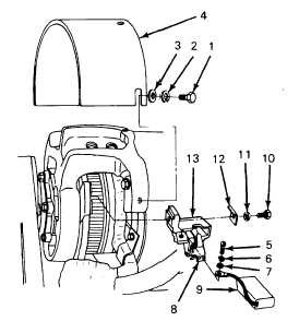
Remove three screws (1), lockwashers (2), flatwashers (3), and
cover plate (4).
4.
Remove screw (5), lockwasher (6), and flat washer (7). Raise
spring (8) and remove brush (9) from brush holder (13).
5.
If required, remove clamping block bolt (10), lockwasher (11),
and clamp (12). Remove brush holder (13).
INSTALLATION
6.
Position brush holder (13) in generator and install clamping block
bolt (10), lockwasher (11), and clamp (12). Finger tighten only.
7.
Raise spring (8) and install new brush (9) in brush holder (13).
Release spring. Install screw (5), lockwasher (6), and flat
washer (7).
4-86


