TM 55-2210-223-12
TO 45A2-2-14-41
2-9.
OPERATION OF BRAKE SYSTEM (cont)
(2)
Depression of the independent brake valve handle whenever the handle is in RELEASE position will cause
the release of any automatic brake application existing on the locomotive.
(3)
Depression of the independent brake valve handle with it somewhere in the application zone will release
the automatic application only to the value corresponding to the position of the handle in the application
zone.
d.
Emergency Brake Valve.
(1) The emergency brake valve is located near the
fireman's position. It is installed at the end of a
branch pipe from the brake pipe. It provides a
means of obtaining an automatic emergency
brake application from a point other than the
brake valve.
(2)
The emergency brake valve should be used
only in case of actual danger, and then should
be left open until the train stops. After the
operating lever has been pulled, it must be
manually reset before brake pipe can be
charged.
2-10. PRESTART INSTRUCTIONS
a.
Do the before (B) operation PMCS in Table 2-1 and paragraphs 2-8 and 2-9.
b.
Refer to paragraph 2-3 for location and ensure the following air valves and cocks are CLOSED:
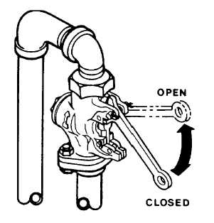
NOTE
Cutoff cocks with bent handles are open (in) when
the handle is parallel with the flow of air. Cutoff
cocks with straight handles are open (in) when the
handle is perpendicular to the flow of air.
(1)
Automatic drain valves in the air reservoirs (The manual valve is opened by turning clockwise, closed by
turning counterclockwise.)
(2)
Trainline hose cutout cocks at each end of the locomotive (If locomotive is connected in multiple-unit
operation, these cocks are OPEN.)
(3)
Dead engine valve
2-28