TM 55-2210-223-12
TO 45A2-2-14-41
Section III.
OPERATION UNDER USUAL CONDITIONS
2-8.
GENERAL
a.
This section covers procedures you will normally be using in operating the 60-ton, diesel-electric locomotive.
b.
Specific instructions are given for starting, operating, stopping, parking, and shutting down the locomotive.
c.
Throughout this section, guidelines are given for adjusting control settings and operating techniques as well as
the specific operating procedures so that you will be able to readily respond to different situations when you
operate the locomotive.
CAUTION
Know the capabilities of your locomotive. Do not
try to make it exceed these limitations.
Know your operator controls and indicators before starting and operating your locomotive.
2-9.
OPERATION OF BRAKE SYSTEM
a.
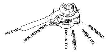
Automatic Brake Valve.
(1)
RELEASE (Running) Position. This position is for charging the brake system and releasing the locomotive
and train brakes. It is located with the brake valve handle at the extreme left of the quadrant.
(2)
MINIMUM REDUCTION Position. This position is located with the brake valve handle against the first
raised portion on the quadrant to the right of RELEASE position. With the brake valve handle moved to
this position, a minimum of brake force is applied.
(3)
SERVICE Position.
This
position
consists of a sector of brake valve handle
movement to the right of RELEASE position.
In moving the brake valve handle from left to
right through this sector, the degree of brake
application is increased until, with the handle
at the extreme right of this sector, the handle
is in FULL SERVICE position and a full
service brake application is obtained.
(4)
SUPPRESSION Position. This position is used during brake pipe testing and on brake systems that have
penalty and safety control brake protection. The brake system on this locomotive does not contain penalty
or safety control features.
2-26


