TM 55-2210-224-34
3-33. GAGE LIGHT RESISTOR AND WHEEL-SLIP RELAY RESISTOR (cont)
REMOVAL (cont)
4. Tag and remove electrical leads from gage light
resistors.
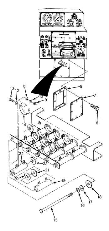
5. Remove eight screws (6), cover (7), and gasket (8).
6. Remove two nuts (9), lockwashers (10), flat washers
(11), flat washers (12), capscrews (13) and jumper
(14).
7. Remove capscrew (15), lockwasher (16), flat washer
(17), insulator (18), gage light resistor (19) insulators
(20), and (21), gage light resistor (22), and insulator
(23).
TEST
8. Use a multimeter and perform a resistance tests on
the resistors. Gage light resistors (19) and (22) are
150 ohms ±5%. Wheel slip relay resistor (4) is 1
ohm. If these reading are not obtained, replace
defective resistors.
INSTALLATION
9. Position insulator (23), gage light resistor (22),
insulators (21) and (20), gage light resistor (19),
insulator (18), flat washer (17), lockwasher (16), and
capscrew (15).
10. Position jumper (14) and install two capscrew (13),
flat washer (12) and (11), lockwasher (10), and nuts
(9).
11. Position gasket (8) and cover (7) and install eight
screws (6).
12. Connect electrical leads to gage.
13. Position insulator (5), wheel slip relay resistor (4),
insulator (3), lockwasher (2), and capscrew (1).
14. Close electrical equipment cabinet door.
3-134