TM 55-2200-001-12
Sec. 6-Fig. 44
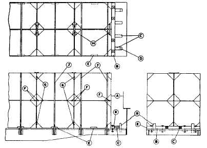
PONTOONS, STEEL, DOUBLE-DECKED-RECTANGULAR SECTIONS-FLAT CARS
Item No. of Pcs.
Description
A
Brake wheel clearance. See Fig. 2.
B
2 per car.
6 in. x 8 in., length equal to width of load. Locate against ends of load and secure each to floor
with four 5/8 in. dia. bolts and washers, as shown.
C
4 ea. Item "B".
Each to consist of three pieces of 2 in. x 6 in., length to suit. Locate two between Items "B" and
"D" and two suitably spaced, as shown. Secure lower pieces to floor with five 30-D nails and
top pieces to those below in like manner.
D
4 per car.
End stakes, length sufficient to extend 9 in. above floor. Locate, as shown, in end stake pockets.
Where end stake pockets are not available, apply two additional Items "C" at each end of load.
E
As required.
3/8 in. x 3 in. x 4 in. x 15 in. angles. Locate as shown, against outside of each unit. Secure each
to floor with three 3/8 in. x 2 in. lag screws or five drive screws prior to loading.
F
As required.
5/8 in. dia. bolts. Locate, as shown, between each unit in top andbottom layers.
G
As required.
5/8 in. dia. bolts. Locate, as shown, between each side by side unit, at top of top layer, and at
bottom of bottom layer.
H
As required.
1/4 in. x 2 in., plates, length to suit. Locate two, as shown, crossed between units in top layers
and secure at each location with one 5/8 in. dia. bolt. Only one Item "H" required at outside
end of end units.
J
As required.
2 in. x .050 in. high tension bands. Locate two over top of side by side units at ends, and one
over top of intermediate side by side units, as shown. Secure to opposite stake pockets.
See General Rules 4, 5, 7, 9, 10, 11, 14 and 15 for further details.
E-54