TM 55-2200-001-12
Sec. 6-Fig. 39
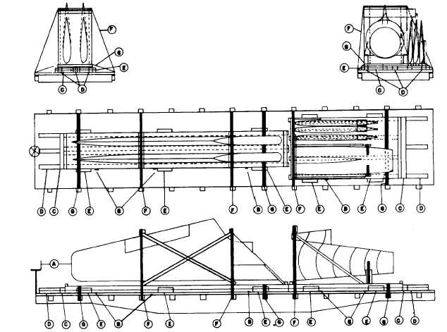
AIRCRAFT WINGS AND AFT SECTION MOUNTED ON WOOD FRAME, UNBOXED ON SKID BASE-FLAT CARS
Item No. of Pcs.
Description
A
Brake wheel clearance. See Fig. 2.
B
6 per wing, 4 ea.
Anti-Skid Plates, pattern 63. Locate between skids of units and floor, as shown. Load must be
per AFT Section.
stenciled on both sides in one Inch letters to read, "Anti-Skid Plates".
C 1 ea. end of load.
Each to consist of two pieces 2 in. x 4 in. length equal to width of load. Secure lower piece to
floor with six 30-D nails and top piece to one below in like manner.
D
3 ea. Item "C".
Each to consist of two pieces 2 in. x 4 in. x 24 in. Locate suitably spaced, as shown, against Item
"C". Secure lower piece to floor with six 30-D nails and top piece to one below in like manner.
E
6 ea. per wing
Each to consist of two pieces, 2 in. x 4 in. x 24 in. Locate at each side of load as shown. Secure
unit; 4 ea. per
lower piece to floor with four 30-D nails and top piece to one below in like manner.
AFT Section.
F
2 per wing sec-
2 in. x .050 in. high tension bands. Locate as shown, attaching to opposite stake pockets of car.
tion. 1 per AFT
Substitute, if desired, steel cable 3/8 in. x 6 x 7.
Section.
G
2 per wing sec-
2 in. x .050 in. high tension bands. Locate as shown, attaching to opposite stake pockets of car.
tion. 1 per AFT
Section.
See General Rules 4, 5, 7, 9, 10, 11, 14 and 15 for further details.
E-49