TM 55-2200-001-12
Change 3
Sec. 6-Fig. 64 (Rev.-9-1977)
(Drawing Redrawn 9-1977)
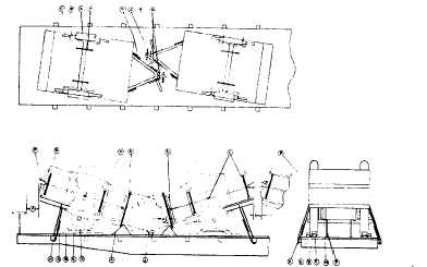
TRAILERS, 1 1/2 TON CARGO, DOUBLE DECKED-FLAT CARS
Item
No. of Pcs.
Description
A
Brake wheel clearance. See Fig. 2.
B
4 per unit.
Blocks, pattern 18. Locate against front and rear of wheels and secure each to floor with three
40-D nails. Substitute, if desired, at each location blocks, patterns 16 or 17.
C
4 per unit.
2 in. x 4 in. x 12 in. Locate against block, pattern 18, lengthwise of car, and secure to floorwith
four 30-D nails. Not required when blocks, patterns 18 or 17 are used.
D
As required.
Suitable material, such as waterproof paper, burlap, etc. Locate bottom portion underneath
Items "E", top portion to extend 2 in. above Items "E".
E
2 per unit.
Each to consist of two pieces of 2 in. x 4 in. x 86 in. and one piece 2 in. x 6 in. x 36 in. lumber.
Nail the 2 in. x 6 In. piece to the edge of one of the 2 In. x 4 in. pieces with five 12-D nails.
Place against tire with Item "D" In place and nail to car floor through the 2 in. x 4 in. piece
to the lower one in like manner. (See pattern 88, page 8, section 6).
F
2 per unit.
1 1/4 in. x .050 In. high tension bands with anchor plates, pattern 84. Locate over axle at each
side of unit and secure each plate to floor with eight 20-D cement-coated nails.
G
1 per unit.
Each to consist of two pieces of 2 in. x 4 in. x 18 in. Locate, as shown, against draw bar, and se-
cure lower piece to floor with three 30-D nails and top piece to one below in like manner.
H
2 per unit.
Wire rope, 3/8 inch, 6 x 19, IWRC, single strand. Attach one at each side of frame or to tiedown
points at rear of trailer and to stake pockets on same side of rail car. Metal fillers or thimbles
sufficient to provide a suitable radius must be used to protect wire rope at stake pockets
and at vehicle tiedown points and must be applied so as to prevent dislodgment. Cable
clips must be applied In accordance with General Rules 15d and 15n.
J
2 per unit.
1 1/4 in. x .050 in. high tension bands with anchor plates, pattern 84. Locate one over lunette
and one through lunette eye, as shown, and secure each plate to floor with eight 0-D cement-
coated nails.
K
2 per unit.
1 1/4 in. x .050 in. high tension bands with anchor plates, pattern 84. Locate, as shown, through
front lifting lug on each side, and secure each plate to floor with eight 20-D cement-coated
nails.
L
6 per unit.
1 3/4 in. x 1 5/8 in. x 7 3/4 in., hardwood. Locate in stake pockets of upper and lower units, as
shown, and secure to prevent displacement.
M
2 per unit.
4 in. x 4 in. x 8 3/4 in., contoured at bottom to fit over axle. Locate, as shown, between body of
lower unit and axle at each side, before top unit Is loaded, and secure In position with No.
8 gage black annealed wire.
N
4 per unit.
1 1/4 in. x .050 in. high tension bands. Locate, as shown, through outside stake pockets of upper
and lower units.
O
2 per unit.
1 1/4 in. x .050 In. high tension bands. Locate one on each side, as shown, and pass through
lifting lugs of units.
P
As required.
Two strands, No. 8 gage black annealed wire. Attach one at each side of tall gate and to body
of unit.
Q
1 per unit.
Each to consist of two pieces of 2 in. x 4 in., length sufficient to provide 8 in. clearance between
tow bars of units. Locate, as shown, and secure lower piece to floor with three 30-D nails
and top piece to one below in like manner.
See General Rules 1, 2, 3, 4. 5, 9, 11, 14, 15 and 19-B for further details.
E-80