TM 55-2200-001-12
Change 3
Sec. 6-Fig. 65-A (Rev.-10-1981)
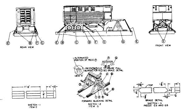
SEMI-TRAILER 12,000-15,000-18,000 LBS.-FLAT CARS
Item
No. of Pcs.
Description
A
Brake wheel clearance. See Fig. 2, Sec. 1.
B
4
Blocks, pattern 16. Locate 45 degree portion in back of outside rear wheels and in front of
outside front wheels. Secure heel of the block to car floor with three 40-D nails and toenail
that portion under the tire to the car floor with two 40-D nails before Items "C" and "F"
are applied.
C
2
Each to consist of one piece of 2 in. x 6 in. x 90 in., lumber and three pieces of 2 in. x 4 in. x
90 in., lumber. Sketch 1 nail one edge of the 2 in. x 6 in. x 90 in., piece to the bottom 2 in. x
4 in. x 90 in., piece with 12-D nails spaced eight inches apart. Then place against the tire
and nail to the car floor through the 2 in. x 4 in., piece with six 30-D nails. Nail the other
two pieces of 2 in. x 4 in. x 90 in., to the one below in the same manner.
D
Vacant.
E
6
Wire rope, 1/2 in. diameter, 6 x 19 IWRC located as shown. Installed at 45 degree maximum
angle, in a complete loop from car stake pocket through the tie-down device on the trailer.
Secure with four 1/2 inch cable clips on each A-ire rope. Thimble, 1/2 inch, must be used at
the stake pocket to protect the wire rope and secured to the tire rope with one 1/2-inch
cable clip.
F
1 ea. Item "C."
Suitable material such as waterproof paper, burlap, etc. Locate bottom portion under Item
"C," the top portion to extend two inches above Item "C."
G
1 ea. unit.
Forward blocking detail, Piece numbers 1 to 10 inclusive. See Sketches 2 and 3.
E-83