Sec. 3--Fig. 1 (Rev.-10-1968)
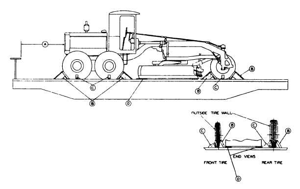
FOUR AND SIX WHEEL MOTOR GRADERS (WITH PNEUMATIC TIRES), LENGTHWISE-FLAT CARS
Item
No. of Pcs.
Description
A
Brake wheel clearance. See Fig. 2, Sec. 1.
B
16 or 8
Blocks, pattern 2. Locate two against front and back of each front wheel, two in front of each
intermediate wheel and two in back of each rear wheel. Nail each to floor with two 60-D, three
40-D and one 20-D nail in heel and one 40-D nail in each side of block.
For six wheel units weighing 10,000 lbs. or less, and for all four wheel units, use one Item "B" at
each location.
C
6
Blocks, pattern 3. Locate all against either inside or outside of each wheel and nail each to floor
with two 60-D, three 40-D and one 20-D nail in heel and one 40-D nail in each side of block.
D
2
1 in. x 6 in. x 24 in. Locate longitudinally under blade of unit, suitably spaced as shown, and
secure each to floor with three 10-D nails.
*When the unit is shipped in a preserved condition, by or for the Department of Defense, the
blade is to be elevated to maximum position and secured to the grader frame with 1/2 in. 6 x
19 preformed wire rope, length to suit, and two 1/2 in. cable clips. Mechanical or hydraulic
blade controls must be placed in closed position and wired.
If so equipped, hand brakes must be tightly set and levers wired.
See General Rules 4, 5, 7, 9, 14, 19-A, 19-B and Fig. 1-B for further details.
F-3