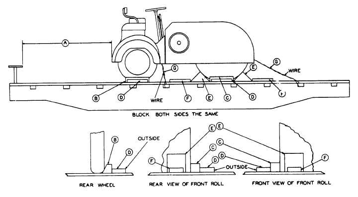
Sec. 3--Fig. 28
ROAD ROLLERS WITH ONE SOLID ROLL AND TWO PNEUMATIC TIRED WHEELS, LENGTHWISE-FLAT CARS
Item
No. of Pcs.
Description
A
Brake wheel clearance. See Fig. 2, Sec. 1.
B
2 ea. machine
Blocks, pattern 23 beveled to fit contour of tire. Locate one against outside of each front wheel
and toe-nail to floor with four 30-D nails.
C
2 ea. machine
4 in. x 4 in. x 21 in. Locate one against each outside face of front roller and toe-nail to floor
with four 30-D nails.
D
4 ea. machine
2 in. x 6 in. x 18 in. Locate one against each Item "B" and "C" and nail each to floor with three
30-D nails.
E
4 ea. machine
Blocks, pattern 24. Locate two against each end and in line withend of roller. Nail each to floor
with five 40-D nails.
F
1 ea. Item
2 in. x 6 in. x 18 in. Locate one on floor against each Item "E" and nail to floor with three 30-D
"E"
nails.
G
4 ea. machine
Each to consist of eight strands of No. 9 gage wire. Pass four wires around frame and through
stake pocket. Overlap ends of wire and twist taut with rod, bolt or pipe, secured to prevent
working loose.
If so equipped, hand brakes must be tightly set and levers wired.
See General Rules 4, 5, 7, 9, 14, 15, 19-A, 19-B and Fig. 1-B for further details.
F-19


