Sec. 3-Fig. 24 (Rev.-10-1968)
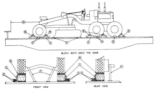
SIX WHEEL MOTOR GRADERS (WITH PNEUMATIC TIRES), LENGTHWISE-FLAT CARS
Item
No. of Pcs.
Description
A
Brake wheel clearance. See Fig. 2, Sec. 1.
B
10
Blocks, pattern 17. Locate one in front and back of each front wheel, one in front and back of
each intermediate wheel and one in back of each rear wheel. Nail each to floor with five 30-D
nails in heel and one 30-D nail in each side of block.
C
4
2 in. x 8 in. x 6 ft. Locate one against the outside of each front and each intermediate wheel.
Nail to each Item "B" with five 30-D nails.
D
8
Each to consist of two blocks, 2 in. x 4 in. x 18 in. Locate one against center of each Item "C".
Nail lower piece to floor with three 30-D nails and top piece to the one below with three 30-D
nails.
E
2
Blocks, pattern 18. Locate one against the outside of each rear wheel. Nail each to floor with
three 30-D nails in heel and one 30-D nail in each side of block.
F
6
1¼ in. x .035 in. high tension bands with twelve eight-hole anchor plates, pattern 19. Locate
two over each end of each axle and nail each plate to floor with eight 30-D nails.
G
2
1 in. x 6 in. x 24 in. Locate longitudinally under blade of unit, suitably spaced as shown and
secure each to floor with three 10-D nails.
*When the unit is shipped in a preserved condition, by or for the Department of Defense, the
blade is to be elevated to maximum position and secured to the grader frame with ½ in. 6 x
19 preformed wire rope, length to suit, and two ½ in. cable clips. Mechanical or hydraulic
blade controls must be placed in closed position and wired.
If so equipped, hand brakes must be tightly set and levers wired.
See General Rules 4, 5, 7, 9, 14, 15, 19-A, 19-B and Fig. 1-B for further details.
F-15