TM 55-2210-224-34
4-8. AIR COMPRESSOR ASSEMBLY (cont)
ASSEMBLY (cont)
56.
Position gasket (164), shim pack (163), and end plate (162) on housing (171) and install six capscrews (161).
Torque capscrews to 72.5 +2.5 lb-ft (101.5 <+3.5 N.m). Refer to table 4-1 and check for end clearance of
bearing (167). If tolerance is not correct, remove end plate and add or remove shims as necessary to meet the
requirement.
57.
Assemble oil pump (154) by assembling gear (160), spacer (159), cam (158), and oil pump housing (157).
58.
Install spring (156), plunger (155),
oil pump (154), two gaskets (153), and cover (152). Secure with six
capscrews (151). Torque capscrews to 7 +1 lb-ft (9.8 +1.4).
59.
Install tube elbow (150), street elbow (149), adapter (148), and oil pressure gage (147).
60.
Install oil tube and screen (146), check valve (145), and adapter (144). Position oil line (143) and connect oil line
fittings (142) and (141).
61.
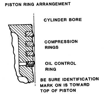
Assemble high-pressure piston assembly (126) by
the following:
a.
Install
oil
ring
(139),
and
three
compression rings (138) on piston (140).
Stagger the ring gaps.
b.
Position connecting rod (137) in piston
(140) and install piston pin (136). Install
capscrew (135). Torque capscrew to 37.5
+2.5 lb-ft (52.5 +3.5 N.mT. Install lockwire
(134).
62.
Assemble low-pressure piston assembly (120) by the following:
a.
Install oil ring (132) and three compression rings (131) on piston (133). Stagger the ring gaps.
b.
Position connecting rod (130) in piston (133) and install piston pin (129). Install capscrew (128). Torque
capscrew to 37.5 +2.5 lb-ft (52.5 +3.5 N.m). Install lockwire (127).
4-26


