Sec. 6-Fig. 22
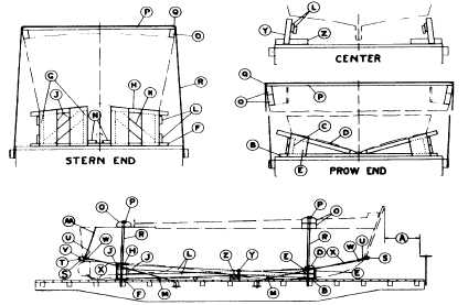
BOATS, LANDING CRAFT-FLAT CARS
Item
No. of Pcs.
Description
A
Brake wheel clearance. See Fig. 2.
B
1
2 in. x 12 in., length to suit. Locate on floor under prow end of boat, as shown, and secure with eight 30-D nails.
C
2
3 in. x 12 in., length to suit. Locate, as shown, and secure to Item "B" with three 30-D nails before application of
Item "B"
D
2
3 in. x 12 in., length to suit. Locate, as shown, and secure to Items "B" and "C" with three 30-D nails at each
location.
E
4
2 in. x 12 in., length and cut to suit. Locate, as shown, and secure to Items "B" and "D" with three 30-D nails at
each location.
F
1
2 in. x 12 in., length to suit. Locate on floor under stern end of boat, as shown, and secure with eight 30-D nails.
G
4
3 in. x 12 in., length to suit. Locate, as shown, and secure each to Item "F" with three 30-D nails before application
of Item "F"
H
2
3 in. x 12 in., length to suit. Locate, as shown, and secure to Items "G" with three 30-D nails at each location.
J
8
2 in. x 12 in., length and cut to suit. Locate, as shown, and secure to Items "F", "G" and "H" with three 30-D nails at
each location.
K
2
2 in. x 6 in., length and cut to suit. Locate, as shown, and secure to Items "F", "H" and "G" with two30-D nails at
each location.
L
4
2 in. x 6 in., length to suit. Locate, as shown, and secure to each Item "C" and outside Items "G" with three 30-D
nails at each location.
M
4
4 in. x 6 in., wedges. Locate suitably spaced under keel, as shown, and secure each to floor with two 30-D nails.
N
2
2 in. x 6 in. x 12 in. Locate, as shown, and secure each to Item "F" with two 30-D nails.
O
4
Filler pieces, length, height and width to suit, minimum thickness 4 in. Locate, as shown.
P
2
2 in. x 6 in., length to suit. Locate, as shown, and secure to Items "O" with two 30-D nails at each location.
Q
4
Protection angles, 20 gage, 4 in. wide, applied so as to prevent displacement.
R
2
5/8 in. x 6 x 7 steel cable, doubled. Locate, as shown, over Items "O", "P" and "Q", and pass through opposite
stake pockets.
S
3
4 in. x 6 in., length to suit. Locate, as shown, one on prow and two on stern end.
T
1
3/16 in. x 3 in. x 7 ft. metal bridle support, attached to Items "U" and "S" on stern end.
U
4
3/16 in. x 3 in. metal bridle straps. Locate over each end of Item "S" on prow end and outside ends of Items "S"
and "V" on stern end.
V
2
4 in. x 6 in., length and tapered to suit. Secure to outside ends of Items "S" on stern end.
W
4
3/4 in. bolts. Attach to Items "U" and "X", as shown.
X
4
3/4 in. diameter rods. Attach to each Item "U" and pass through stake pockets and 1/2 in. x 4 in. x 12 in. plate, as
shown.
Y
2
2 in. x 4 in., length to suit. Locate, as shown, and secure to Items "L" and Z" with three 30-D nails at each location.
Z
2
4 in. x 6 in., length to suit. Locate, as shown, and toe-nail each to floor with four 30-D nails.
AA
2
1/2 in. diameter rod. Secure to top of boat and to Items "U" on stern end, as shown.
See General Rules 4, 5, 7, 9, 11, 14, 15 and 19-A for further details.
E-23