Sec. 4-Fig. 33-B (New-1-1976)
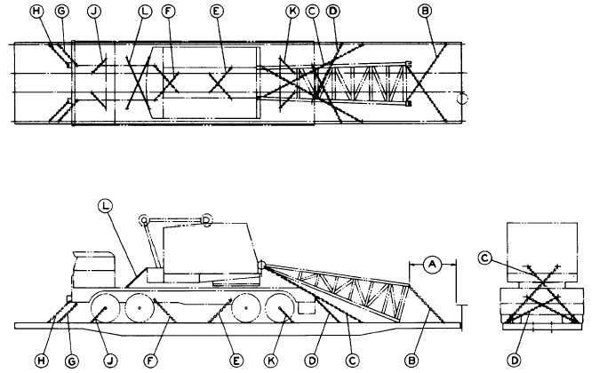
ROTATING CRANES, MAXIMUM WEIGHT, 125,000 LBS., HAVING PNEUMATIC TIRES, FLAT CARS WITH
CHAIN
TIE-DOWNS ASSEMBLIES AND TIE-DOWN CHANNELS
Item No. of Pcs.
Description
A
Brake wheel clearance. See Fig. 2, Sec. 1.
B
2 ea. boom
1/2 in. alloy chain tie-down. Attach from boom end connections to opposite outside tie-down
channels.
C
2 ea. boom
1/2 in. alloy chain tie-down. Attach from boom feet to opposite outside tie-down channels.
D
2
1/2 in. alloy chain tie-down. Attach from tow hooks at rear of carrier to opposite outside tiedown
channels.
E
2
1/2 in. alloy chain tie-down. Attach from tie-down holes in bottom flange plate on truck frame to
opposite inside tie-down channels.
F
2
1/2 in. alloy chain tie down. Attach from lifting lugs on outriggers to opposite inside tie-down
channels.
G
2
1/2 in. alloy chain tie-down. Attach from tow hooks at front of carrier to outside tie-down
channels.
H
2
1/2 in. alloy chain tie-down. Attach from front carrier counterweight brackets to outside tie-down
channels.
J
2
1/2 in. alloy chain tie-down. Attach from front axle to inside tie-down channels.
K
2
1/2 in. alloy chain tie-down. Attach from rear axle to inside tie-down channels.
L
2
1 1/4 in. diameter rod. Attach from rotating crane base to carrier base to prevent rotating while
in transit.
NOTES:
1. Gantry must be telescoped to lowest position for shipping and locked in place to prevent displacement while in
transit.
2. Positive swing lock must be activated to lock rotator positively to base.
F-55