Sec. 4--Fig. 31 (Rev.--1962)
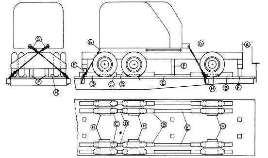
ROTATING CRANE, HAVING PNEUMATIC TIRES, BOOM DETACHED-FLAT CARS
Item No. of Pcs.
Description
A
Brake wheel clearance. See Fig. 2, Sec. 1.
B
16
8 in. x 8 in. x 36 in., hardwood. Locate on floor against tires and secure each with 3/4 in. dia.
bolts with nuts and washers.
C
8
8 in. x 8 in. x 8 in., hardwood. Locate on floor against tires and secure each with two 3/4 in. dia.
bolts.
D
4
3 1/2 in. x 5 in., hardwood, long enough to fit between Items "C". Nail each to floor with four 60-
D nails.
E
4
3 1/2 in. x 5 in., hardwood, long enough to fit between Items "B". Nail each to floor with eight
60-D nails.
F
6
8 in. x 8 in., hardwood, length to suit. Locate under front center and rear of crane and toenail
each to floor with four 60-D nails.
G
4
1 1/4 in. dia. rods, with threaded ends, length to suit. Attach two to boom connection brackets
and two to counterweight. Pass bottom ends through stake pockets and 1/2 in. x 4 in. x 10 in.
plates underneath stake pockets on opposite sides of car. 1 in. dia. rods may be used on
machines weighing 45,000 lbs. or less. Substitute, if desired, 5/8 in. x 6 x 7 steel cable,
doubled.
H
4
Each to consist of two pieces 2 in. x 4 in. x 18 in. Locate one against each front and each rear
wheel. Nail lower pieces to floor with four 20-D nails and top pieces to those below in like
manner.
For proper location of load on car, see Fig. 34.
Machines equipped with locking devices must have such devices placed in locked position by shippers.
See General Rules 4, 5, 9, 14, 15, 19, 19-A and 19-B for further details.
F-50