Sec. 4--Fig. 32
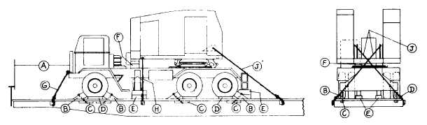
ROTATING CRANE, HAVING PNEUMATIC TIRES, BOOM DETACHED--FLAT CARS
Item No. of Pcs.
Description
A
Brake wheel clearance. See Fig. 2.
B
8
8 in. x 8 in. x 21 1/2 in., hardwood. Locate one in front and at rear of each front wheel, one in
front of each intermediate wheel, and one behind each rear wheel. Secure each with one 3/4
in. dia. rod, with nuts. Pass rod through plate washer, Item "B", floor and Item "C". Use
bevel washer under Item "C".
0
8
4 in. x 4 in. x 18 in., hardwood, or 1/2 in. x 4 in. x 18 in. plates. Locate under floor as
required.
D
6
4 in. x 4 in. x 28 in., hardwood. Locate one against outside of each wheel. Nail each to floor
with six 40-D nails.
E
4
Each to consist of two pieces, 6 in. x 8 in. x 18 in., hardwood. Locate under each side at center
and rear of chassis. Toe-nail lower piece to floor with six 40-D nails and top piece to the one
below with four 40-D nails.
F
2
6 in. x 6 in. x 15 in., hardwood. Locate between Rotating and body portion of unit. Secure to
prevent displacement.
G
2
1/2 in. dia. steel cable, doubled. Attach one to each side of body of unit, at front, and to stake
pocket.
H
2
1/2 in. dia. steel cable, doubled. Attach one to each side of rotating portion of unit and to
opposite stake pocket.
J
2
1/2 in. dia. steel cable, doubled. Attach one to each side of rotating portion of unit and to
opposite stake pocket.
For proper location of load on car, see Fig. 34.
Machines equipped with locking devices must have such devices placed in locked position by shippers.
See General Rules 4, 5, 7, 9, 14, 15, 19, 19-A and 19-B for further details.
F-51