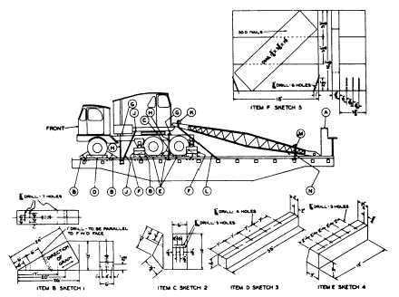
Sec. 4--Fig. 33
ROTATING CRANES, HAVING PNEUMATIC TIRES-FLAT CARS
Item No. of Pcs.
Description
A
Brake wheel clearance. See Fig. 2.
B
8
Blocks, 6 in. x 10 in. x 24 in., Sketch 1. Locate one in front and one in rear of each front wheel,
one in front of each intermediate wheel and one in rear of each rear wheel. Secure each to
floor with one 3/4 in. dia. x 22 in. rod passed through floor and 2 in. x 4 in. x 12 in. cleat
under floor, five 60-D nails in heel of block and toe-nail each side of block with one 60-D nail.
0
4
Blocks, 6 in. x 7 1/2 in. x 10 in., Sketch 2. Locate one in front of each rear wheel and one in
rear of each intermediate wheel. Nail each to floor with five 60-D nails.
D
4
Blocks, 4 in. x 4 in. x 35 in., Sketch 3. Locate one against inside and outside of each front
wheel. Nail each to floor with four 60-D nails.
E
4
Blocks, 3 in. x 3 in. x 12 in., Sketch 4. Locate one against outside of each rear and
intermediate wheel. Nail each to floor with five 60-D nails.
F
4
Blocks, each to consist of three pieces 5 5/8a in. x 5 5/8 in. x 18 in. and one piece 1 5/8 in. x 5
3/8 in. x 19 in., Sketch 5. Locate one under each outrigger on each side of unit. Toe-nail
each to floor with six 60-D nails.
G
2
4 in. x 6 in. x 62 in. Locate on top of frame of unit, secure with Items "H".
H
4
3/4 in. dia. rods. Pass through each end of Items "G" and through 1/2 in. x 4 in. x 10 in.
plates under stake pockets or 4 in. x 4 in. x 18 in. hardwood cleats, or 1/2 in. x 4 in. x 18 in.
plates under floor.
J
2
1 1/4 in. dia. rods, with threaded ends, length to suit. Attach two to front of rotating portion and
pass bottom ends through stake pockets and 1/2 in. x 4 in. x 10 in. plates underneath stake
pockets on opposite sides of car, or through floor and 4 in. x 4 in. x 18 in. cleats, or 1/2 in. x
4 in. x 18 in. plates under floor on opposite sides of car. 1 in. dia. rods may be used on
machines weighing 45,000 lbs. or less. Substitute, if desired, 5/8 in. x 6 x 7 steel cable, doubled.
K
1
4 in. x 4 in. x 4 ft. Locate on top of boom and secure with Item "L".
L
2
1 1/4 in. dia. rods, with threaded ends, length to suit. Pass through Items "K" and 1/2 in. x 4 in.
x 10 in. plates underneath stake pockets on opposite sides of car. 1 in. dia. rods may be
used on machines weighing 45,000 lbs. or less. Substitute, if desired, 5/8 in. x 6 x 7 steel
cable, doubled. When boom is detached, attach rods to boom connection bracket.
M
1
2 in. x 4 in., long enough to extend beyond sides of boom. Secure with two Items "N".
N
2
3/4 in. dia. rods. Pass through each end of Item "M" and through floor and 4 in. x 4 in. 18 in.
cleat, or 1/2 in. x 4 in. x 18 in. plate under floor.
Items "K", "M" and "N" not required when boom is detached.
On units where counterweight of rotary portion extends beyond rear of frame, overhanging portion must be
supported by suitable built-up frame.
Machines equipped with locking devices must have such devices placed in locked position by shippers.
For proper location of load on car, see Fig. 34.
See General Rules 4, 5, 9, 14, 15, 19, 19-A and 19-B for further details.
F-52


