Sec. 4--Fig. 27 (Rev.--3-1965)
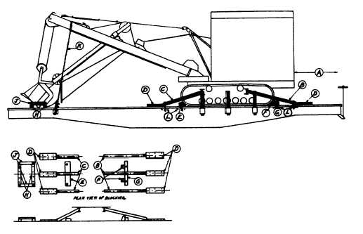
MACHINES ON WHICH BOOM ONLY ROTATES-FLAT CARS
Item No. of Pcs.
Description
A
Brake wheel clearance. See Fig. 2, Sec. 1.
B
3
4 in. x 4 in., length to suit, outside braces bolted, center braces nailed.
C
3
4 in. x 4 in., length to suit, outside braces bolted, center braces nailed.
D
6
3 in. x 8 in., nailed to floor with six, 60-D nails.
E
1
5 in. x 8 in. x 30 in., secured to floor with two 1/2 in. bolts.
F
2
5 in. x 5 in. x 8 in., against crawler portion, nailed with three 60-D nails.
G
1
5 in. x 5 in. x 30 in., secured to floor with two 1/2 in. bolts.
H
2
4 in. x 4 in. x 36 in., nailed to floor with four 60-D nails.
J
2
2 in. x 4 in. x 24 in., secured with two 2 in. bolts passing through Items "H" and floor.
K
1
3/8 in. x 6 x 19 steel cable, doubled. Attach to front of boom and body of car. Substitute, if
desired, 5/8 in. dia. rods or 8 strands No. 11 gage wire.
L
8
4 in. x 4 in. x 18 in., hardwood cleat, or 1/2 in. x 4 in. x 18 in. plate.
Other suitable blocking may be used in cases where the design of the machine does not permit the use of the
blocking specified.
For proper location of load on car, see Fig. 34.
*Machines equipped with locking devices, including those with adjustable treads, must have such devices placed
in locked position by shippers.
See General Rules 4, 5, 9, 10, 14, 15, 19 and 19A for further details.
F-46