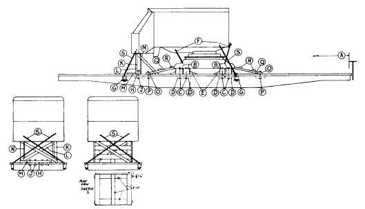
Sec. 4--Fig. 26
CRAWLER TYPE SHOVELS, CRAWLERS REMOVED, ROTATING BODIES, BOOMS DETACHED-FLAT CARS
Item No. of Pcs.
Description
A
Brake wheel clearance. See Fig. 2, Sec. 1.
B
4
10 in. x 10 in., hardwood, length to suit, higher and wider if necessary. Locate under base of
machine, near each end. Secure each to floor with four 5/8 in. dia. bolts.
O
16
5/8 in. dia. bolts, with nuts and washers, long enough to pass through Items "B", floor and Items "D".
D
As required.
4 in. x 4 in. x 18 in., hardwood, or 1/2 in. x 4 in. x 18 in. plates.
E
8
4 in. x 6 in. x 12 in., hardwood wedges. Nail two to floor against each Item "B" with four 30-D
nails in each.
F
4
1 1/4 in. dia. rods, length to suit. Attach two to front and two to rear of rotating portion and to
opposite sides of crawler structure. Substitute, if desired, 5/8 in. x 6 x 7 steel cable, doubled,
at each location.
Where machines are equipped with two brackets cast integral on both rotating portion and
crawler structure, Items "F", need not be crossed but may be applied to same side of machine.
G
As required.
1/2 in. x 4 in. x 10 in. plates.
H
1
6 in. x 6 in., hardwood, length to suit, for machines weighing 120,000 lbs. or less; 8 in. x 8 in.,
hardwood, for machines weighing more than 120,000 lbs. Secure to floor with four 5/8 in. dia.
bolts.
J
4
5/8 in. dia. bolts, with nuts and washers, long enough to pass through Item "H", floor and Items
"D".
K
As required.
Two 6 in. x 6 in., hardwood, for machines weighing 120,000 lbs. or less; four 8 in. x 8 in.,
hardwood, for machines weighing more than 120,000 lbs. They must be long enough to fit
between Item "H" and body of machine. Toe-nail each to Item "H" with four 30-D nails.
L
2
2 in. x 6 in., hardwood, length to suit. Locate diagonally. Secure to Items "K" and to Item "H" at
bottom, with four 30-D nails at each location.
M
2
2 in. x 4 in. x 18 in., hardwood. Nail to floor against Item "H" with six 30-D nails in each.
N
2
2 in. x 6 in., length to suit. Secure top ends to Items "K" and bottom ends to Items "Q" with four
30-D nails at each location.
O
2
4 in. x 6 in., hardwood, length to suit. Secure to floor with four 5/8 in. dia. bolts.
P
8
5/8 in. dia. bolts, with nuts and washers, long enough to pass through Items "O", floor, and
Items "D".
Q
As required.
Four 6 in. x 6 in., hardwood, for machines weighing 120,000 lbs. or less; eight 6 in. x 6 in.,
hardwood, for machines weighing more than 120,000 lbs. They must be long enough to fit
between Items "O" and body of machine. Toe-nail to Items "O" with four 30-D nails.
R
4
2 in. x 6 in., hardwood, long enough to extend beyond outside Items "Q". Secure to Items "Q"
with three 20-D nails at each location.
S
4
1 1/4 in. dia. rods, length to suit, for machines weighing 120,000 lbs. or less; 1 1/2 in. dia.
rods for machines weighing more than 120,000 lbs. Attach to front and rear of rotating portion.
Pass bottom ends through and secure underneath stake pockets and Items "G" on opposite
sides of car. Substitute, if desired, 5/8 in. x 6 x 7 steel cable, doubled.
Cribbed blocking, per Sketch 1, may be substituted for Items "H", "J", "K", "L", "M" and "N".
Detached parts must be loaded as far from car sides and ends as practicable and secured to prevent displacement
Machines equipped with locking devices must have such devices placed in locked position by shippers.
For proper location of load on car, see Fig. 34.
See General Rules 4, 5, 7, 9, 14, 15, 19 and 19-A for further details.
F-45