TM 55-2200-001-12
Change 4
NATO UNCLASSIFIED
8.
c.
(5)
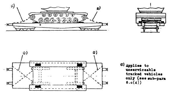
Figure 14 illustrates the complete tie-down arrangement.
Figure 14
d.
Securing of Wheeled Vehicles by Type I Arrangement:
(1)
A chock as described in Figures 1, 2 and 3 is to be placed at the front and rear of each wheel except
for double-axle assemblies where chocks are placed only at the outside and for twin-wheel
assemblies where chocks are placed only at one wheel in such a manner that the wheeled vehicle
rests between the chocks as if in a cradle mounting.
(2)
Two tie-down 3s described in sub-para 7.a. are to be attached at either end of each wheeled vehicle.
As far as possible, these tie-down are to be arranged crosswise and transverse to the direction of
travel; they should be only moderately tensioned.
-13-
cp
NATO UNCLASSIFIED
Change 4 AA-14