TM 55-2200-001-12
Change 4
NATO UNCLASSIFIED
(5)
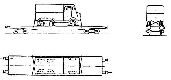
Figure 15 illustrates the complete tie-down arrangement.
Figure 15
e.
Securing of Wheeled Vehicles by Type II Arrangement:
(1)
A chock as described in sub-para 6.b.(2)(b) is to be placed at the front and rear of each wheel except
for double-axle assemblies where chocks are placed only at the outside and for twin-wheel
assemblies where chocks are placed at one wheel in such a manner that the wheeled vehicle rests
between the chocks as if in a cradle mounting.
(2)
In accordance with Annex II to RIV, additional chocks are to be nailed to the wagon floor at an angle
of 50' against the outside or inside flanks of all wheels of vehicles over 1,500 kg in weight, single-
axle trailers and semi-trailers, irrespective of their weight (see Figure 16, in circle)
(3)
In addition, two tie-down as described in sub-para 7.b. are to be attached at either end of each
wheeled vehicle. These tie-down should be only moderately tensioned.
-14-
cp
NATO UNCLASSIFIED
Change 4 AA-15


