TM 55-2210-223-12
TO 45A2-2-14-41
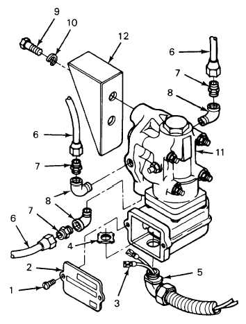
4-26. SANDER CONTROL VALVE (cont)
REMOVAL
4.
Open electrical equipment cabinet and set battery switch to OPEN.
5.
Remove two machine screws (1) and cover (2). Tag and disconnect wires (3). Remove conduit nut (4) and pull
conduit elbow (5) from bottom of sander control valve (11).
6.
Disconnect three air lines (6).
7.
Remove three male half unions (7) and street elbows (8). Remove two capscrews (9) and lockwashers (10).
Remove sander control valve (11) from bracket.
INSTALLATION
8.
Position sander control valve (11) on bracket and install two lockwashers (10) and capscrews (9).
9.
Apply antiseize tape to the threads of three street elbows (8) and male half unions (7). Install street elbows and
male half unions. Connect three air lines (6).
10.
Position conduit elbow (5) in bottom of sander control valve (11) and install conduit nut (4). Connect wires (3)
and remove tags. Position cover (2) on valve and install two machine screws (1).
11.
Open electrical equipment cabinet and set battery switch to CLOSE.
12.
Start locomotive (para 2-11). After air pressure buildup, check sander control valve for proper operation.
4-66