TM 55-2210-223-34
TO 45A2-2-14-22
3-34. VOLTAGE REGULATOR (cont)
REMOVAL (cont)
3.
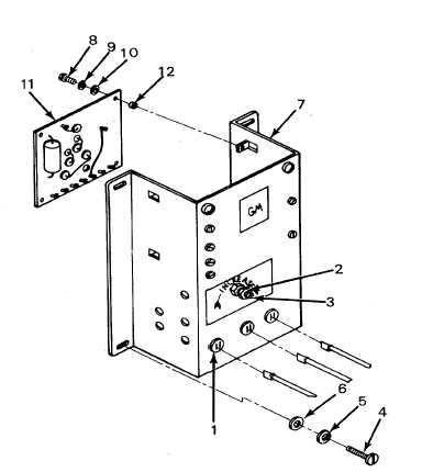
Remove four screws (4), lockwashers (5), flat washers (6), and voltage regulator (7).
REPAIR
4.
Remove four screws (8), lockwashers (9), flat washers (10), panel control board (11), and four grommets (12).
Tag and disconnect wires from panel control board.
INSTALLATION
5.
Connect wires to panel control board and remove taqs.
6.
Install four grommet (12). Position panel control
board (11) and secure with four flat washers
(10), lockwashers (9), and screws (8).
7.
Connect voltage regulator wires and perform
voltage test in step 1 above. If reading of 74 1
volt is not obtained, remove control board,
return board to stock, and perform step 8. If 74
volts 1 is obtained proceed to step 9-and
continue with installation procedures.
8.
Tag and disconnect voltage regulator wires, and
replace entire voltage regulator.
9.
Install voltage regulator (7) and secure with four
flat washers (6), lockwasher (5), and screws (4).
10.
Connect voltage regulator wires in accordance
with wiring diagram and remove tags.
11.
Loosen locking nut (2) and turn rheostat (3) to
minimum reading.
12.
Connect multimeter leads between positive side of charge fuse and negative side of battery switch.
13.
With engine running the multimeter reading should indicate between 62 and 70 volts.
14.
Place throttle in No. 8 position and adjust rheostat to maintain 74 volts. Allow components to warm up, and
adjust voltage as necessary until constant 74-volt reading is attained. Lock rheostat (3) in place by tightening
locking nut (2).
15.
Shut down engine. (TM 55-2210-223-12)
3-116


