TM 55-2210-223-34
TO 45A2-2-14-22
3-36. MAIN GENERATOR (cont)
DISASSEMBLY (cont)
16.
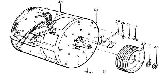
Remove nut (28) and lockwasher (29). Reinstall nut to serve as a stop when pulley (30) is removed.
17.
Install pry bars between stator frame cover (55) and pulley (30).
18.
Use a torch and heat pulley (30). Apply pressure to pulley and loosen pulley.
19.
Remove nut (28) and pulley (30).
20.
Remove keyway (31) from armature shaft.
21.
Install lifting eye near fan end of main generator.
22.
Install a heavy-duty strap (7000-lb (3175 kg) minimum capacity) through cover hole on each side of main
generator.
WARNING
Components of this locomotive are heavy and may be awkward to handle. Use correct lifting procedures,
indicated lifting devices, and/or assistance from other personnel to avoid injury.
23.
Use suitable lifting devices and simultaneously lower fan end and raise pulley end until main generator is in a
vertical position with pulley end facing up. Slowly lower main generator to ground.
24.
Remove eight bolts (32) and washers (33).
25.
Use spring to hold brushes from holder and lift brushes far enough out of brush box to prevent them from sliding
back against the commutator.
26.
Wrap a piece of insulating paper around the commutator to protect it while handling.
27.
Install lifting eyes on each side of stator frame cover (55).
3-136


