TM 55-2210-223-34
TO 45A2-2-14-22
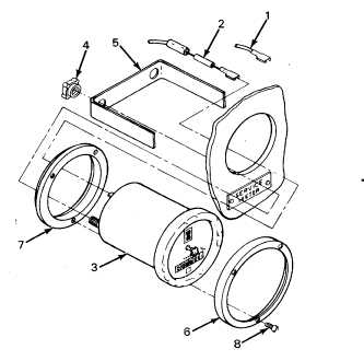
3-13. SERVICE METER GAGE
This task covers:
a.
Removal
b.
Test
c.
Installation
INITIAL SETUP
Tools
Tool kit SC 4940-97-CL-E12
REMOVAL
1.
Set battery switch to OPEN position.
2.
Tag and disconnect wire (1) and resistor (2)
from meter (3).
3.
Remove two plastic nuts (4) and remove clamp
(5).
4.
Remove meter (3) from front of meter panel.
5.
Remove chrome ring (6), spacer (7), and three
screws (8) from meter (3) as one assembly.
6.
Remove three screws (8) and remove chrome
ring (6) from spacer (7).
TEST
7.
Connect a variable DC power supply to + and -
side of the service meter and apply 40 VDC to
meter. Check that time advances on meter
face.
INSTALLATION
8.
Install chrome ring (6) on spacer (7).
9.
Install three screws (8) into chrome ring (6).
10.
Install assembled chrome ring (6) and spacer (7)
on meter (3).
11.
Install meter (3) into meter panel.
12.
Install clamp (5) and two plastic nuts (4) on back
of meter (3).
13.
Connect resistor (2) and wire (1) to proper
terminals. Remove tags.
3-48