TM 55-2210-223-24
TO 45A2-2-14-22
3-19. MULTIPLE-UNIT RECEPTACLE
This task covers:
a.
Removal
d.
Inspection
g.
Assembly
b.
Disassembly
e.
Repair
h.
Installation
c.
Cleaning
f.
Test
INITIAL SETUP:
Tools
Test Equipment
Personnel
Tool kit SC 4940-97-CL-E12
Multimeter 6625-01-139-2512
2
Megohmmeter 6625-00-456-7442
REMOVAL AND DISASSEMBLY
WARNING
High voltage is used in the operation of equipment. Do not be misled by the term LOW VOLTAGE.
Potentials as low as 50 volts may cause death.
Remove rings, bracelets, wristwatches, and neck chains before working around the locomotive. Jewelry
can catch on equipment and cause injury, or may short across an electrical circuit and cause severe burns
or electrical shock.
Use caution when removing cover hinge shaft. Spring is under pressure and may cause injury to
personnel when released from cover hinge shaft.
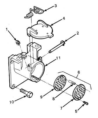
1.
Set battery switch to OPEN position.
2.
Remove external snapring (1), cover hinge shaft
(2), spring (3), and housing cover (4).
3.
Remove three screws (5) securing pin assembly
(6) to receptacle housing (11).
4.
Remove pin assembly (6) from receptacle
housing (11).
5.
Remove insulator plate (7).
6.
Tag and disconnect wires from 32 pins (8) as
required.
7.
Remove insulator plate (9) if required.
8.
Remove four bolts (10) and receptacle housing
(11).
3-60