
with 35 volts across AG to N (make AG
should not drop more than 3/6 inch due to
positive). Coil should be warm.
its own weight when the main panel is in
position on the locomotive.
(7) Set contact spring tight as possible and
still permit relay to seal at pick-up voltage
(5) Set reverse current relay armature gap to
without fail. Relay must not float in or out.
1/16 inch at center of coil core. Adjust
stationary contacts to just touch the
(8) With 32 volts across AG to N, pass
movable contact and lock them. Re-
current through relay B3 to AG. (Make B3
adjust armature gap to 5/32 and lock it.
positive.) Relay should drop out at 4 to 12
Contact gap should then be 13/64.
amperes without floating.
(6) Adjust armature spring so relay closes
Section XI. SPEED INDICATING EQUIPMENT
installation measure the wheel diameter and set the
wheel-wear adjustment in the transformer-resistor box.
Refer to paragraph 98.
c. Indicator.
(1) The temperatures where the indicator is
mounted should never exceed 140 F.
Indicator will operate more accurately at a
temperature of 75 10 F. Figure 32
shows mounting dimensions.
(2) Handle indicator with care to avoid
damaging jewel bearings.
Do not
hammer on the panel on which the
indicator is mounted.
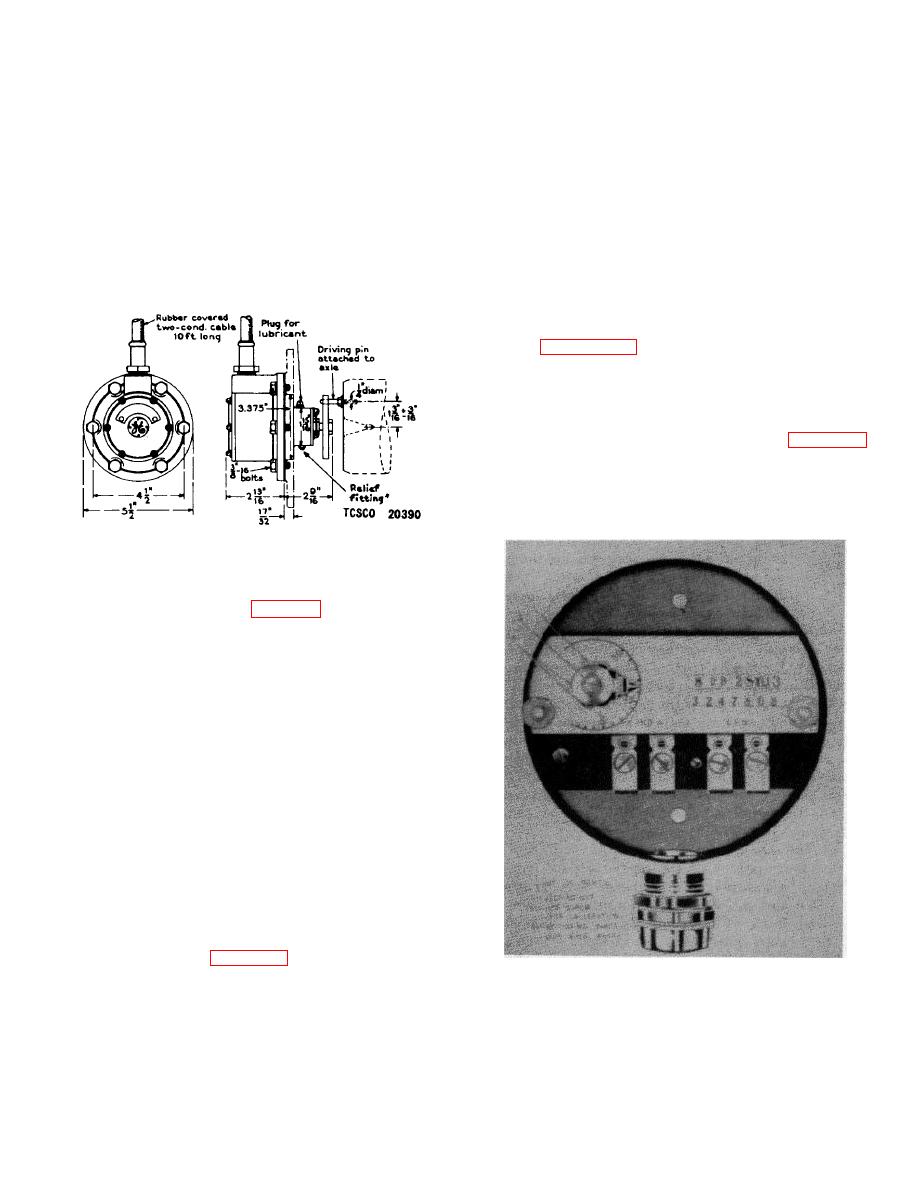
Figure 31. CM-4 Generator assembly method.
97. Installation
a. Mounting Generator. Install a driving pin on the
end of the axle as shown in figure 31. Bolt the special
journal box cover into position. Turn the generator rotor
so that the driving arm engages with the pin on the axle.
Carefully position the generator against the journal box
cover checking that there is clearance between the pin
and generator. Bolt the generator, with the drain hole
down, to the journal box cover using standard 3/8-16
bolts. Check that the generator shaft is concentric with
the wheel axle. Gaskets are provided to make an oil-
tight connection. Place a piece of 3/4-inch hose,
clamped at both ends, over the generator cable for
protection.
b. Transformer-Resistor Box.
Mount the
transformer-resistor box in any convenient location
which is protected from dirt and moisture. Particular
attention must be paid to the temperature of tile site. It
is recommended that the site have a temperature range
of 75 10 F. The temperature should never rise
above 120 F. Temperatures up to 120 F. will not
damage the box but will introduce temporary errors in
proportion to the rise. Figure 32 shows the mounting
Figure 32. Transformer-resistor box with
dimensions of the transformer-resistor box.
On
dimensions.
62
