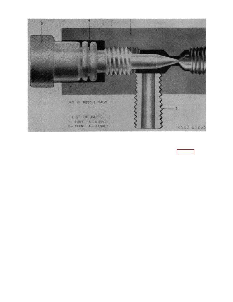
Figure 40. Bell ringer needle valve.
minimum and fitted with oversize piston 1.0248 inch
b. To disassemble valve drive out handle pill (6)
diameter maximum, 1.0240 inch minimum at port end.
and remove handle (3). Unscrew cap (4) from body (1)
c. If clapper fulcrum pin shows excessive
and push out rotor (2). Refer to figure 39.
clearance in the oilite bearings (7), pin and bearings
c. Seating surfaces on rotor (2) and body (1) may
should be replaced. After bearings are pressed in place,
be lapped in, or refaced, many times before valve has
peen over metal on outside to hold bearings in place.
to be condemned.
Ream bearings to 0.3760 inch diameter after pressing in
d. When seats are refaced remove all sharp edges
if fulcrum pin does not revolve freely.
Before
and burrs. Renew gasket (7) if damaged.
reassembling, all parts must be clean. Lubricate with
light oil and test assembled ringer.
107. Bell Ringer Needle Valve
To adjust cadence, close needle valve screw and
106. Bell Ringer Operating Valve
gradually unscrew until proper cadence is acquired. Do
a. An occasional drop of light oil is all this valve
not unscrew more than two full turns as opening through
will require to provide years of trouble-free service.
body to ringer is maximum. The O-ring gasket prevents
air leaks and holds valve adjustment.
Section XIV. OIL FILTER
when loosened, swing away from the cover so as to
108. Description
permit its removal easily. The cover is sealed by means
a. The lubricating oil filter has a radial flow
of a wide vellumoid gasket.
repackable wastex element. The cover is held to the
top ring by means of four steel eyebolts. These bolts,
67


