
resistor box setting, if necessary.
To make the
adjustment, loosen the locking nut, taking care not to
disturb the setscrews on the hub of the dial, and set the
dial to correspond with the diameter of the wheel driving
the generator. Tighten the locking nut. Check setting to
see that it has not been disturbed when locking.
b. Zero-Set. The indicators are equipped with an
external zero-adjusting screw in the front of the case.
The pointer may be set on zero, when the indicator is
de-energized, by turning the zero adjuster with a
screwdriver at the same time gently tapping the front of
the cover.
particular transformer-resistor box and the two must
always be used together. However, generators of the
Figure 32 - Continued.
same type may be interchanged with no effect on the
accuracy of the system. Check the speed-indicator
calibration occasionally by observing the time over a
measured mile.
To check the operation of the
equipment when it is removed from the locomotive, a
calibration curve (fig. 35) shows the relation between
generator rpm and instrument indication in miles per
hour for wheel diameters between 30 inches and 40
inches.
d. Generator. It is important that ,a watertight joint
be maintained at the point where the cable enters the
generator. Do not remove the leads from the generator
unless it is necessary to replace either generator or
leads. If it is necessary to remove the generator,
disconnect the leads at the connection box.
On
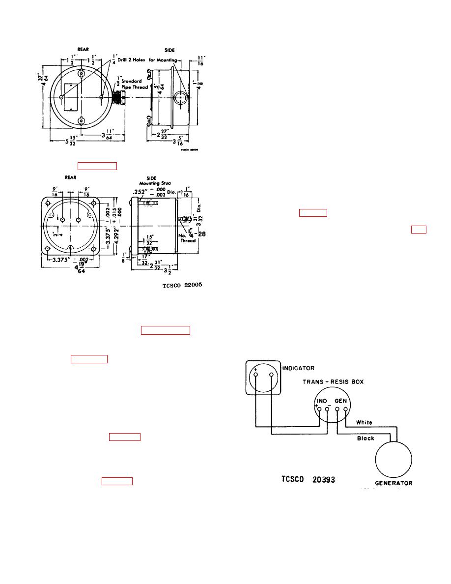
Figure 33. Speed indicator mounting dimensions.
replacing the cover plate of the terminal box, cement
the cover gasket in place with gasket cement. Take
(3) Check that the pointer is on the zero
every precaution to see that no water is allowed to enter
mark. If it is off, make the zero-set
the generator.
adjustment. Refer to paragraph 98.
e. Lubrication.
The generator is permanently
d. Connections.
lubricated; therefore, it will be necessary to lubricate it
(1) Make connections in accordance with
only at overhaul with high-temperature grease.
stranded copper wire.
(2) Make a good ground connection between
the locomotive frame and the truck on
which the generator is mounted. The
resistance of the ground circuit may be
checked by temporarily disconnecting the
auxiliary ground lead to the transformer-
resistor box at the point X on connection
diagram (fig.
ohmmeter. The resistance as measured
at this point should be less than 10 ohms.
98. Maintenance
diameter at regular intervals and adjust the transformer-
Figure 34. Wiring diagram for type CM-4 generator.
63
