
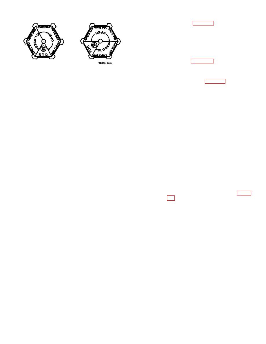
simple gage, figure 24, is employed. This
gage is used for both standard and
inverted valve by turning it over,
depending on type of valve to be
checked.
e. Checking and Adjusting Standard Valves.
(1) Upper valve stem.
and adjust the final gap and length
Figure 24. Valve setting gage.
of new upper valve stems. Remove
the magnet cap and insert the gage
the order of their usual liability of
as shown on figure 25. Flat-file the
occurrence.
top of the upper stem until the
(a) Dirt on the valve seat (e).
0.056-inch gage will admit air to the
cylinder with a slight leak out the
(b) Weak battery or low voltage applied
exhaust and the 0.052-inch gage
to coil.
will close the exhaust valve tight.
(c) Dirt under the magnet armature (h).
The final air gap is then between
(d) Valve stem (k) worn down so that
the two, or approximately 0.054
armature strikes the core (m) before
inch.
New stems have excess
the valve seats.
length and should be ground to a
(2) To remove stem (k) it is not necessary to
tight seat before adjusting the gap.
shut off the air. First remove the cap over
Directions for grinding are included
the armature and lift out the armature
in h below.
which is not fastened in any way. Next
(b) In service, it is permissible to allow
place a finger on one hand over the
the upper stem and seat to wear
magnet valve exhaust port (f) and press
until the final gap is approximately
down on top of the valve stem with a
0.032 inch. The 0.066-inch gage
finger of the other hand and then raise the
will at this point fail to unseat the
finger quickly. The valve stem will be
lower valve to admit air to the
raised by the air pressure and can be
cylinder and the upper stem must
readily lifted out and the end of the valve
be stretched by peening or a new
wiped clean.
stem used.
(3) A weak battery will sometimes give a
(2) Lower valve stem. The same gage, figure
sufficient pull to unset the lower valve but
not enough to close the exhaust. The
has been adjusted, to adjust the travel
obvious remedy is to charge the battery.
and the length of the lower valve stem.
(4) Another possible cause of a blowing
Use the 0.088-inch gage.
This will
exhaust valve, i. e. worn down stem (k),
probably cause the valve to unseat and
is very unlikely to occur until after the
blow due to excess length of the lower
equipment has been in service for several
stem. The upper end of lower stem
years. If this stem is found to be too short
should then be flat-filed until the 0.088-
it can be slightly stretched by "peening"
inch gage will not touch but the 0.070-inch
the shank.
gage will unseat the lower stem. The total
d. Valve Gaging.
gap is then approximately 0.086 inch and
the travel is 0.086 inch minus 0.054 inch
(1) In order to obtain satisfactory operation
or 0.032 inch. In service, it is permissible
from the electro pneumatic valves, it is
to allow the lower stem to wear as long as
necessary to maintain the "travel of the
the condemning gage 0.066 inch makes
valve" and the final gap between the
the lower valve blow when the upper stem
magnet armature and core, within certain
is new. If it does not, the travel has then
limits.
reached 0.012 inch and the lower
(2) After a considerable period of service the
valves wear down and it is necessary to
refit or replace them.
In order to
accurately determine their condition a
52
