TM 55-2210-224-34
3-64. TRACTION MOTOR ASSEMBLY (cont)
DISASSEMBLY (cont)
17.
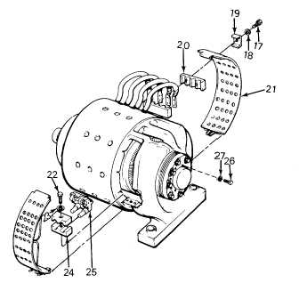
Remove eight capscrews (26) and lockwashers
(27).
18.
Install two 3/8-16 by 15-inch (381 mm) guide
bolts through two holes in end plate (40) into
bearing housing (35).
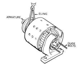
19.
Install two jack bolts in the tapped holes
provided and jack armature (37) out of motor
housing (42) on the two guide bolts.
20.
When armature (37) is 2 to 3 inches (50.8 to 76.2 mm) from the end of the frame, install a sling around armature.
Use a suitable lifting device and support and remove armature. Remove the guide bolts from bearing housing
(35).
21.
Remove four flat-head screws (28), bearing cap
(29), and gasket (30).
22.
Straighten two tab bars (31) and remove four
capscrews (32), tab bars, and clamping plate
(33).
23.
Use puller from disassembly tool kit and remove
ball bearings (34) and bearing housing (35).
Use a press and press ball bearings from
bearing housing.
3-237