TM 55-2210-224-34
3-64. TRACTION MOTOR ASSEMBLY (cont)
REMOVAL
1.
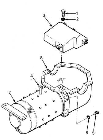
Remove traction motor (7) from gear unit (8) by the following:
a.
Remove lockwire from three capscrews
(1)
and lockwashers (2). Remove hypoid oil pan
(3).
b.
Measure and record the following:
(1)
End play of intermediate shaft
(2)
Distance from intermediate shaft to face of
pinion
(3)
Backlash of ring gear when moved into
mesh
WARNING
Components of the traction motor are
heavy and may be awkward to handle.
Use
correct
lifting
procedures,
indicated
lifting
devices,
and/or
assistance from other personnel to
avoid injury.
c.
Install a 1-inch eye bolt (4) into the hole
provided in bottom of motor frame. Use a
suitable lifting device and take up on eyebolt
until weight is just taken up.
d.
Use a punch and punch-mark motor and gearcase for proper installation. Reach through fan openings and
remove 12 capscrews (5) and lockwashers (6).
e.
Install two jack screws in the two tapped holes provided in the gearcase and jack motor (7) from gear unit (8).
3-234


