TM 55-2210-224-34
3-64. TRACTION MOTOR ASSEMBLY (cont)
DISASSEMBLY
2.
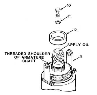
Install motor lifting bracket (9) and place motor on floor in a vertical position adequately supported on motor-nose
suspension and suitable support device.
NOTE
The disassembly tool kit and the following procedures are recommended for removal of the hypoid
pinion. However, any tool that does not cause damage to the pinion or other parts, and any method
that can be accomplished in a safe manner, may be used.
3.
Remove bolt (10) and tab washer (11). Use a puller and remove oil slinger (
12) to expose armature shaft
threads.
4.
Check pinion bore for clean and smooth
condition. Fill chamber in armature and pinion
shaft to within 1 inch (25.4 mm) of top of pinion
bore with oil. Do not trap air while filling.
5.
Use the piston puller rod from disassembly tool
kit as a pump in the armature-shaft chamber
and purge chamber of air.
WARNING
To prevent the barrel from coming
loose, causing injury to personnel,
check that that it screws all the way
down on the armature shaft threads.
If unable to screw the barrel all the
way down, remove the barrel and
repair the damaged threads.
6.
Remove pull rod, leaving piston in place, and
screw the barrel of disassembly tool kit onto the
armature shaft.
7.
Screw cap assembly of disassembly tool kit into
the barrel until 1/8-inch (3 mm) clearance is left
between pinion and cap.
8.
Insert a 1-inch (25.4 mm) diameter bar in hole provided in bolt on cap of disassembly tool kit and steady the cap.
Position socket wrench on bolt.
3-235


